How to Fix Overheating in Tuya C10 Camera Modules
When a Tuya C10-based camera module drops offline after two hours of operation, resets itself without warning, or corrupts a microSD card at high ambient temperature — the root cause is almost always the same: thermal failure, not hardware defect. The symptoms are predictable and reproducible because they follow the thermal behavior of the onboard DSP and wireless chipset at elevated junction temperatures.
This guide covers the thermal design principles that govern C10 module operation, explains why certain installation environments cause failures, and provides specific mitigation steps for each failure mode. For OEM integrators and B2B clients who are embedding these modules into third-party enclosures, this is the documentation that the product datasheet does not include.
How Heat Is Generated Inside a C10 Camera Module
The C10 module contains three primary heat-generating components, each with a distinct thermal signature:
RTL8710BN WiFi SoC (primary heat source). This is the dominant heat source on the module. The RTL8710BN integrates a 125 MHz ARM Cortex-M4F CPU with a full 802.11 b/g/n MAC and baseband processor. Under active P2P streaming or heavy WiFi traffic, the SoC dissipates between 350 mW and 700 mW depending on transmit power and data rate. In still air at room temperature, the die temperature rise above ambient (theta-JA) for the QFN-48 package is approximately 80°C/W — meaning at 500 mW dissipation, the die temperature rises 40°C above the local air temperature.
Camera ISP (Image Signal Processor). The OV9734 or equivalent image sensor includes an onboard ISP that performs demosaicing, noise reduction, and exposure correction at 30 fps. ISP power consumption is relatively constant during active recording, adding approximately 150–250 mW to the thermal load regardless of scene complexity.
Power management ICs (LDOs and DC-DC converters). The 3.3 V and 1.8 V rails are generated from the 5 V USB input through a combination of low-dropout regulators and a single-channel buck converter. LDO regulators dissipate (Vin – Vout) × Iload as heat — at typical operating current (400–500 mA total), the LDO stages collectively dissipate 300–600 mW even at high efficiency.
Total dissipation in active-recording mode: approximately 1.0–1.5 W. In a sealed plastic enclosure with no thermal path to ambient air, this heat accumulates. The internal air temperature rises until the rate of heat generation equals the rate of heat dissipation through the enclosure walls — a steady-state equilibrium that for a small 50×50×30 mm enclosure in still indoor air typically reaches 35–45°C above ambient.
At 25°C room temperature, the internal equilibrium reaches 60–70°C. At 30°C (summer conditions, enclosed ceiling void), it reaches 65–75°C. At these temperatures, the thermal runaway threshold for the RTL8710BN is not yet reached — but the microSD card, which is designed for commercial-grade temperature ranges (0°C to 70°C for standard cards), begins to experience intermittent failures.
Why Sealed Enclosures and Insulation Wrapping Cause Failures
The most common integration mistake made by B2B clients is wrapping the module in electrical insulation tape or enclosing it in a sealed box without ventilation — usually motivated by the desire to make the installation appear clean and professional.
Electrical tape is a thermal insulator. It has a thermal conductivity of approximately 0.2 W/m·K, compared to air (0.026 W/m·K) and aluminum (237 W/m·K). Wrapping the module in tape adds a thin but thermally significant boundary layer between the components and the surrounding air, trapping heat directly against the PCB surface. The heat generated by the SoC cannot escape through this barrier and accumulates on the component-side of the board, raising the temperature of every component within 5 mm of the heat source.
What the thermal imaging actually shows: In a wrapped installation, the SoC temperature reaches the thermal throttling threshold (typically 85°C junction temperature) within 30–45 minutes of continuous operation. The RTL8710BN’s built-in thermal management kicks in: the ARM core reduces its clock frequency from 125 MHz to 62.5 MHz, then to 31.25 MHz in staged steps. At 62.5 MHz, the WiFi MAC processing throughput drops below the threshold required to maintain a stable P2P connection — the module drops offline in the app. If the temperature continues to rise, the chip performs a hard reset to protect the die.
The microSD card secondary failure: Standard microSD cards are rated for operation from 0°C to 70°C commercial temperature range. Cards used in the -25°C to 85°C extended temperature range (industrial grade) cost 3–5× more per unit. At sustained internal temperatures above 65°C, the card’s internal NAND controller firmware begins to exhibit read-retry cycles, ECC failure rate increases, and eventually the card stops responding to commands. In FAT32 filesystem environments, this manifests as “card error,” “card full,” or the inability to write new files — even when the card appears to be empty when mounted on a PC.
Thermal Pad Application: The Correct Method
The correct thermal management approach for C10 module installations uses thermal interface material (TIM) to create a conduction path from the module to the enclosure:
Select the correct thermal pad. The SoC on the C10 module is exposed on the component side — there is no dedicated thermal pad pre-applied. Apply a 1.5 mm thick silicone thermal pad with thermal conductivity of 3–5 W/m·K (commonly rated as “3W/mK” or “5W/mK” thermal pad, available from electronics suppliers). Thinner pads (<1 mm) compress excessively under enclosure pressure and lose thermal contact. Thicker pads (>2 mm) increase thermal resistance beyond what the module can tolerate.
Placement procedure:
1. Power off the module and disconnect all cables.
2. Clean the top surface of the RTL8710BN chip and surrounding components with a dry lint-free cloth. Do not use isopropyl alcohol — it can dissolve the chip marking ink and does not affect thermal performance.
3. Place the thermal pad directly on top of the chip and surrounding area, ensuring full coverage of the SoC and power management ICs. The pad should not extend to the edges of the PCB in a way that creates a risk of shorting any exposed component leads.
4. Route the thermal path: position the module inside the enclosure so that the thermal pad contacts the inner surface of the enclosure wall. The ideal enclosure material is aluminum or steel (high thermal conductivity). ABS plastic is less effective but acceptable if the contact area is large (>15×15 mm).
5. Mechanical retention: ensure the enclosure provides consistent pressure on the thermal pad — the pad must not shift during shipping or handling. Foam tape on the enclosure interior behind the module provides consistent compression.
For plastic-only enclosures with no metallic thermal path: Apply the thermal pad to the SoC and any nearby power ICs, then route it to a flat area of the ABS enclosure with the largest surface area. ABS has a thermal conductivity of approximately 0.3 W/m·K — slow, but with sufficient surface area contact to ambient air, passive dissipation is possible. In a 80×80×50 mm ABS enclosure with a 15×15 mm thermal pad contacting a flat interior wall, the achievable steady-state temperature reduction is approximately 8–12°C compared to no thermal management at all.
Power Supply Separation: The 220V/110V AC-DC Brick Problem
B2B clients frequently embed the C10 camera module inside a modified wall socket or power strip — combining the covert camera with a functioning power outlet. This is one of the highest-risk installation configurations for thermal failure.
The AC-DC step-down module required to convert 220V or 110V mains AC to 5V DC is itself a significant heat source. A typical miniature AC-DC isolated converter module (form factor: DIP or SMD, 24×16×12 mm) dissipates 1–3 W of heat at full load, with efficiency ranging from 75% to 85% depending on load and input voltage. At 220V input, the no-load power consumption alone generates 50–150 mW of heat continuously.
The failure mechanism when modules are stacked: If the AC-DC converter module is mounted directly adjacent to or on top of the C10 camera PCB — a natural mechanical choice when designing a compact dual-function socket — the converter’s thermal output adds directly to the camera module’s thermal environment. The combined heat load in a sealed ABS wall socket enclosure reaches 2–4 W, which in the thermal mass of a wall socket (typically 50–80 g of ABS plastic) raises the internal air temperature to 50–65°C above ambient within 20–30 minutes.
The required separation distance: The C10 module and the AC-DC converter must maintain a minimum of 15 mm of physical air gap in all three axes. This is not a recommendation — it is the minimum distance that allows the AC-DC converter’s heat to dissipate into the enclosure air before reaching the camera module’s inlet air. Stacking the modules directly, even with a thin metal shield between them, is insufficient because the shield acts as a thermal bridge rather than a barrier.
Mechanical layout guidance for wall socket installations:
1. Position the AC-DC converter at the bottom of the enclosure (farthest from the camera lens).
2. Use a metal partition plate between the converter and the camera module if space does not permit 15 mm air gap — the plate must not be mechanically bonded to both modules simultaneously; it should float on silicone thermal pads on both sides.
3. Drill 2–3 mm ventilation holes in the enclosure wall directly above the camera module to allow convection airflow. These holes are invisible from the front in most wall socket designs.
4. Do not seal the enclosure with silicone — leave the bottom edge unsealed by 0.5–1 mm to allow air exchange with the room.
Recording Strategy: Event-Based Mode Reduces Heat by 60%

The most effective software-level thermal mitigation strategy is reducing the module’s active processing time. Every second the ISP is encoding video, the SoC is processing WiFi frames, and the NAND is writing data — all three heat sources are simultaneously active. Reducing recording time proportionally reduces thermal load.
24/7 continuous recording mode: The module records continuously, encoding H.264 video at 1080p / 30fps. SoC power dissipation: approximately 1.2 W sustained. The thermal equilibrium in a sealed ABS enclosure is reached at approximately 55–70°C above ambient within 60–90 minutes.
Event-based (motion detection) recording: The ISP enters a low-power monitoring mode between events, encoding preview frames at approximately 1 fps while the motion detection algorithm scans the scene. Only when motion is detected does the module switch to full 1080p / 30fps encoding. In a typical domestic or office environment, motion-triggered recording produces 30–120 minutes of actual recording per 24-hour period — an 80–90% reduction in active encoding time. SoC power dissipation averages approximately 400–500 mW over 24 hours. The thermal equilibrium in the same enclosure is approximately 18–25°C above ambient — well within safe operating limits for both the SoC and the microSD card.
To switch to event-based recording in the Tuya Smart / Smart Life app:
1. Open the device in the app.
2. Tap the gear icon to access Settings.
3. Select Recording Plan or Storage Settings.
4. Change from Continuous Recording (24h) to Event Recording or Motion Detection.
5. Adjust the motion detection sensitivity slider to suit the environment — for indoor environments with pets, reduce sensitivity to avoid excessive recording events and continued heat generation.
6. Confirm. The change takes effect immediately without a module restart.
For B2B deployments in high-security environments where 24/7 coverage is required, the thermal management steps in the previous sections are mandatory. For general-purpose home or office surveillance, event-based recording eliminates the thermal failure risk entirely.
Passive Ventilation Design for Custom Enclosures
When embedding the C10 module into any custom enclosure, passive ventilation should be treated as a first-class design requirement — not an afterthought.
The convection principle: Hot air rises. In a sealed enclosure, the hottest air accumulates at the top, closest to the heat sources. Ventilation holes at the top of the enclosure allow this hot air to escape by natural convection, drawing cooler room air in through bottom vents. The net effect is a continuous low-rate air change that carries heat away from the components.
Recommended vent pattern for C10 module installations:
1. Cut 3–4 holes of 2–3 mm diameter at the top of the enclosure, directly above the SoC location on the PCB. These are the exhaust vents.
2. Cut 2–3 holes of 2 mm diameter at the bottom of the enclosure, on the opposite face from the camera lens. These are the intake vents.
3. Do not use larger holes — larger holes reduce structural integrity and do not significantly improve airflow at the low pressure differential created by natural convection in a small enclosure.
4. Position the camera module at the top of the enclosure if possible, with the SoC facing toward the exhaust vents.
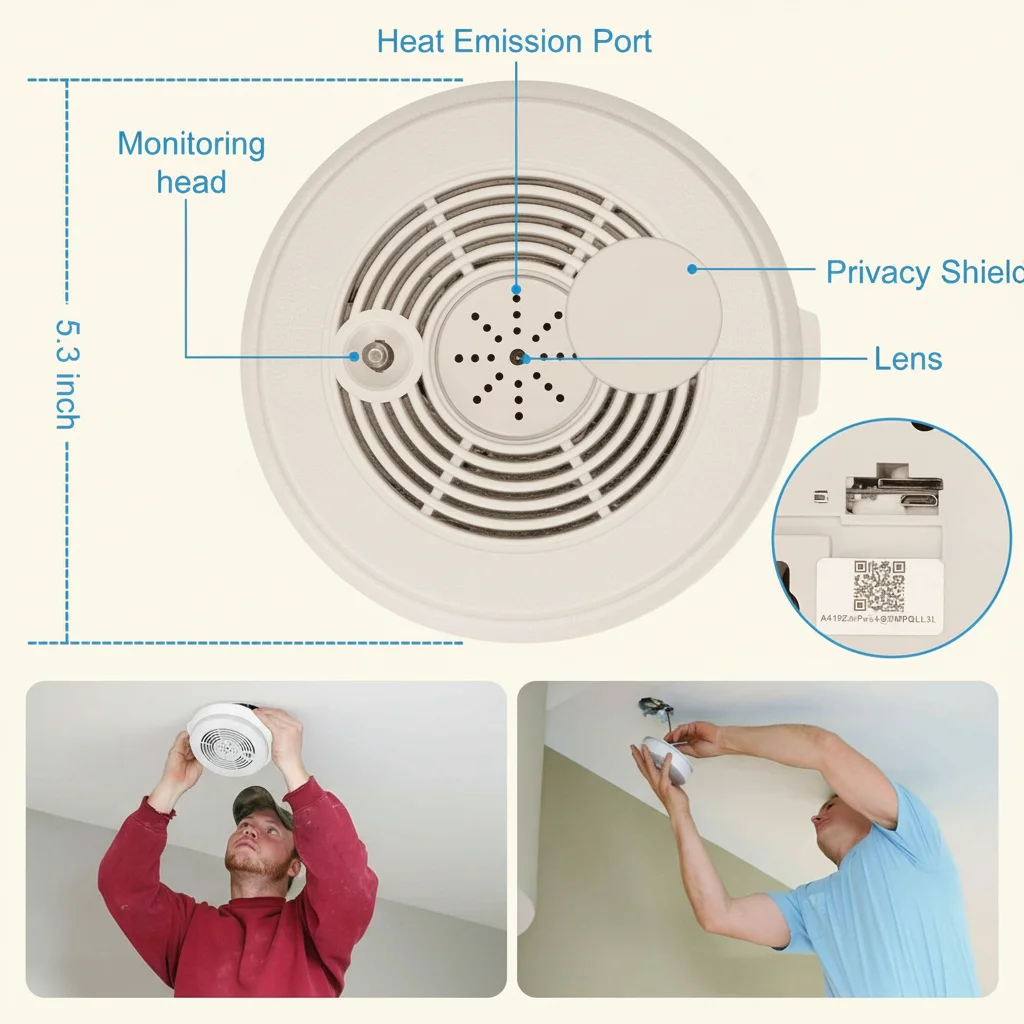
For ceiling void installations (e.g., behind a ceiling-mounted smoke detector or light fixture): The void above a ceiling tile can reach 35–40°C in summer due to heat rising from the room below and insulation above. If the C10 module is installed in such a void, the thermal management steps above are especially critical. Consider routing the WiFi antenna outside the void through a cable gland to a location with better thermal environment — the antenna position has no thermal impact and the cable gland provides a sealed passage that maintains the room’s appearance.
Overheating Diagnosis: Identifying Thermal Failures vs. Other Issues
Not every failure is a thermal problem. Here is how to identify whether a C10 module failure is thermally caused:
| Symptom | Thermal Cause | Other Likely Cause | Diagnostic Action |
|---|---|---|---|
| Device drops offline after 1–2 hours | Thermal throttling at ~85°C junction | WiFi router AP steering | Observe whether the failure correlates with room temperature or duration of continuous recording |
| SD card becomes unreadable after hot period | Card overheating (>70°C) | Card failure / FAT corruption | Remove card, test on PC; test card in a different device at room temperature |
| Device resets without warning | Thermal hard reset (>110°C absolute max) | Firmware crash | If the device resets every time after the same duration, it is thermal; if the timing varies randomly, it is software |
| Recording stops but app still shows live view | ISP / NAND thermal shutdown | Storage full / firmware bug | Check available storage in app; observe whether live view continues after recording stops (it does in thermal NAND shutdown) |
| Device runs fine for days then suddenly fails | Gradual thermal degradation of thermal interface | Random firmware failure | The failure timing in thermal degradation is predictable and reproducible; random timing suggests software |
Frequently Asked Questions
Q: My module is inside an aluminum enclosure. Do I still need a thermal pad?
A: Yes, but the approach changes. Aluminum enclosures conduct heat efficiently, but the thermal resistance at the interface between the PCB and the aluminum is still significant without TIM. Apply thermal pad to the SoC as described, then use thermal compound (Arctic MX-4 or equivalent, applied in a thin smear) at the interface between the PCB and the aluminum wall. The aluminum will act as a spreader, distributing the heat across its surface area and then dissipating it to ambient air. In aluminum enclosures, 8–12°C of reduction is typical compared to the same enclosure with no thermal management.
Q: Can I use a small fan to cool the module?
A: A small 5V DC brushless fan (20×20×5 mm, available from electronics suppliers) can reduce the internal air temperature by 15–25°C and eliminates thermal throttling entirely in almost all sealed-enclosure scenarios. Wire the fan to the 5V and GND rails of the C10 module’s USB input. The current draw of a 5V 20mm fan (60–120 mA) is well within the 500 mA USB spec. Position the fan to blow across the SoC and SD card — not to blow into the lens. The trade-off is audible noise: fans at full speed are typically 18–28 dB, audible in quiet rooms but acceptable for utility rooms and offices.
Q: What temperature does the microSD card actually fail at?
A: Commercial-grade microSD cards (the vast majority of cards sold) are rated for 0°C to 70°C operation. Failure onset typically begins at 65°C with read-retry increases, and becomes catastrophic (card unresponsive) above 72°C. Industrial-grade cards (-25°C to 85°C) are significantly more resistant but add $8–15 per card. For most B2B deployments in climate-controlled environments, thermal management of the enclosure is the more cost-effective solution than specifying industrial-grade storage.
Q: We are installing 200 units across a commercial building. What is the commissioning checklist?
A: For large-scale deployments: (1) Specify industrial-grade microSD cards (or accept a 2–3% annual card failure rate with commercial cards in non-AC environments). (2) Require event-based recording as the default firmware configuration. (3) Require each installation to include a thermal pad and documented thermal path to the enclosure material. (4) Commission a sample of 10 units with a thermocouple measurement inside the enclosure at peak operating temperature (run 2 hours, measure with a K-type thermocouple probe inserted through a vent hole). (5) Set a firmware alert threshold: if the module resets more than once per 7-day period, trigger a maintenance inspection.
Q: The module works fine during the day but fails in the evening. What is happening?
A: This is a classic thermal signature. During the day, the building HVAC is running and the ambient room temperature may be 22–24°C. In the evening when HVAC shuts off, the room temperature rises to 26–30°C — and in enclosed spaces with poor ventilation, the internal enclosure temperature rises by a further 15–20°C. The evening failure temperature threshold is reached at approximately 2–4 hours after HVAC shutdown. Switching to event-based recording solves this without hardware modification.
Conclusion
Thermal failure in C10-based camera modules is a design and installation problem, not a component defect. The RTL8710BN SoC and microSD card are capable of reliable operation at elevated temperatures — provided that heat is conducted away from the module and dissipated to the environment.
The three mandatory requirements for reliable long-term installation are: first, do not wrap the module in insulating material; always apply a thermal pad with a conductive path to the enclosure. Second, maintain physical separation between the C10 module and any AC-DC power conversion components — 15 mm minimum air gap, or a floating metal partition with TIM on both sides. Third, switch from continuous 24/7 recording to event-based motion detection recording wherever possible — this single software change reduces average thermal load by 60–80%.
For B2B clients integrating the C10 module at scale, thermal management should be treated as a first-day design requirement, not a post-deployment troubleshooting exercise. A 15-cent thermal pad and two vent holes cost less than a single warranty return.