
How to Fix Overheating in Tuya C10 Camera Modules
When a Tuya C10-based camera module drops offline after two hours of operation, resets itself without warning, or corrupts a microSD card at high ambient temperature — the root cause is almost always the same: thermal failure, not hardware defect. The symptoms are predictable and reproducible because they follow the thermal behavior of the onboard DSP and wireless chipset at elevated junction temperatures.
This guide covers the thermal design principles that govern C10 module operation, explains why certain installation environments cause failures, and provides specific mitigation steps for each failure mode. For OEM integrators and B2B clients who are embedding these modules into third-party enclosures, this is the documentation that the product datasheet does not include.
How Heat Is Generated Inside a C10 Camera Module
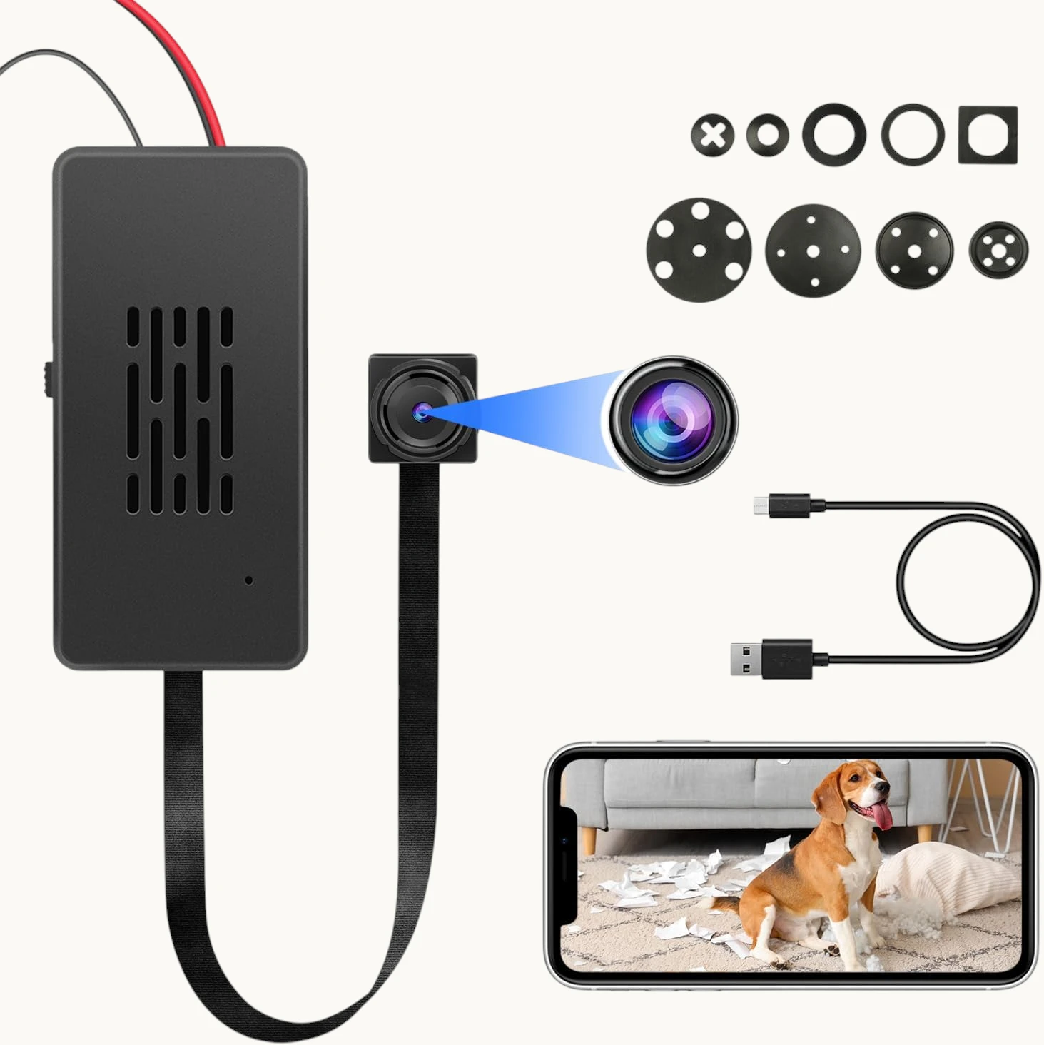
The C10 module contains three primary heat-generating components, each with a distinct thermal signature:
RTL8710BN WiFi SoC (primary heat source). This is the dominant heat source on the module. The RTL8710BN integrates a 125 MHz ARM Cortex-M4F CPU with a full 802.11 b/g/n MAC and baseband processor. Under active P2P streaming or heavy WiFi traffic, the SoC dissipates between 350 mW and 700 mW depending on transmit power and data rate. In still air at room temperature, the die temperature rise above ambient (theta-JA) for the QFN-48 package is approximately 80°C/W — meaning at 500 mW dissipation, the die temperature rises 40°C above the local air temperature.
Camera ISP (Image Signal Processor). The OV9734 or equivalent image sensor includes an onboard ISP that performs demosaicing, noise reduction, and exposure correction at 30 fps. ISP power consumption is relatively constant during active recording, adding approximately 150–250 mW to the thermal load regardless of scene complexity.
Power management ICs (LDOs and DC-DC converters). The 3.3 V and 1.8 V rails are generated from the 5 V USB input through a combination of low-dropout regulators and a single-channel buck converter. LDO regulators dissipate (Vin – Vout) × Iload as heat — at typical operating current (400–500 mA total), the LDO stages collectively dissipate 300–600 mW even at high efficiency.
Total dissipation in active-recording mode: approximately 1.0–1.5 W. In a sealed plastic enclosure with no thermal path to ambient air, this heat accumulates. The internal air temperature rises until the rate of heat generation equals the rate of heat dissipation through the enclosure walls — a steady-state equilibrium that for a small 50×50×30 mm enclosure in still indoor air typically reaches 35–45°C above ambient.
At 25°C room temperature, the internal equilibrium reaches 60–70°C. At 30°C (summer conditions, enclosed ceiling void), it reaches 65–75°C. At these temperatures, the thermal runaway threshold for the RTL8710BN is not yet reached — but the microSD card, which is designed for commercial-grade temperature ranges (0°C to 70°C for standard cards), begins to experience intermittent failures.
Why Sealed Enclosures and Insulation Wrapping Cause Failures
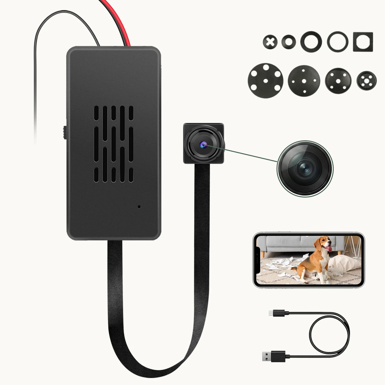
The most common integration mistake made by B2B clients is wrapping the module in electrical insulation tape or enclosing it in a sealed box without ventilation — usually motivated by the desire to make the installation appear clean and professional.
Electrical tape is a thermal insulator. It has a thermal conductivity of approximately 0.2 W/m·K, compared to air (0.026 W/m·K) and aluminum (237 W/m·K). Wrapping the module in tape adds a thin but thermally significant boundary layer between the components and the surrounding air, trapping heat directly against the PCB surface. The heat generated by the SoC cannot escape through this barrier and accumulates on the component-side of the board, raising the temperature of every component within 5 mm of the heat source.
What the thermal imaging actually shows: In a wrapped installation, the SoC temperature reaches the thermal throttling threshold (typically 85°C junction temperature) within 30–45 minutes of continuous operation. The RTL8710BN’s built-in thermal management kicks in: the ARM core reduces its clock frequency from 125 MHz to 62.5 MHz, then to 31.25 MHz in staged steps. At 62.5 MHz, the WiFi MAC processing throughput drops below the threshold required to maintain a stable P2P connection — the module drops offline in the app. If the temperature continues to rise, the chip performs a hard reset to protect the die.
The microSD card secondary failure: Standard microSD cards are rated for operation from 0°C to 70°C commercial temperature range. Cards used in the -25°C to 85°C extended temperature range (industrial grade) cost 3–5× more per unit. At sustained internal temperatures above 65°C, the card’s internal NAND controller firmware begins to exhibit read-retry cycles, ECC failure rate increases, and eventually the card stops responding to commands. In FAT32 filesystem environments, this manifests as “card error,” “card full,” or the inability to write new files — even when the card appears to be empty when mounted on a PC.
Thermal Pad Application: The Correct Method
The correct thermal management approach for C10 module installations uses thermal interface material (TIM) to create a conduction path from the module to the enclosure:
Select the correct thermal pad. The SoC on the C10 module is exposed on the component side — there is no dedicated thermal pad pre-applied. Apply a 1.5 mm thick silicone thermal pad with thermal conductivity of 3–5 W/m·K (commonly rated as “3W/mK” or “5W/mK” thermal pad, available from electronics suppliers). Thinner pads (<1 mm) compress excessively under enclosure pressure and lose thermal contact. thicker pads (>2 mm) increase thermal resistance beyond what the module can tolerate.
Placement procedure:
1. Power off the module and disconnect all cables.
2. Clean the top surface of the RTL8710BN chip and surrounding components with a dry lint-free cloth. Do not use isopropyl alcohol — it can dissolve the chip marking ink and does not affect thermal performance.
3. Place the thermal pad directly on top of the chip and surrounding area, ensuring full coverage of the SoC and power management ICs. The pad should not extend to the edges of the PCB in a way that creates a risk of shorting any exposed component leads.
4. Route the thermal path: position the module inside the enclosure so that the thermal pad contacts the inner surface of the enclosure wall. The ideal enclosure material is aluminum or steel (high thermal conductivity). ABS plastic is less effective but acceptable if the contact area is large (>15×15 mm).
5. Mechanical retention: ensure the enclosure provides consistent pressure on the thermal pad — the pad must not shift during shipping or handling. Foam tape on the enclosure interior behind the module provides consistent compression.
For plastic-only enclosures with no metallic thermal path: Apply the thermal pad to the SoC and any nearby power ICs, then route it to a flat area of the ABS enclosure with the largest surface area. ABS has a thermal conductivity of approximately 0.3 W/m·K — slow, but with sufficient surface area contact to ambient air, passive dissipation is possible. In a 80×80×50 mm ABS enclosure with a 15×15 mm thermal pad contacting a flat interior wall, the achievable steady-state temperature reduction is approximately 8–12°C compared to no thermal management at all.
Power Supply Separation: The 220V/110V AC-DC Brick Problem
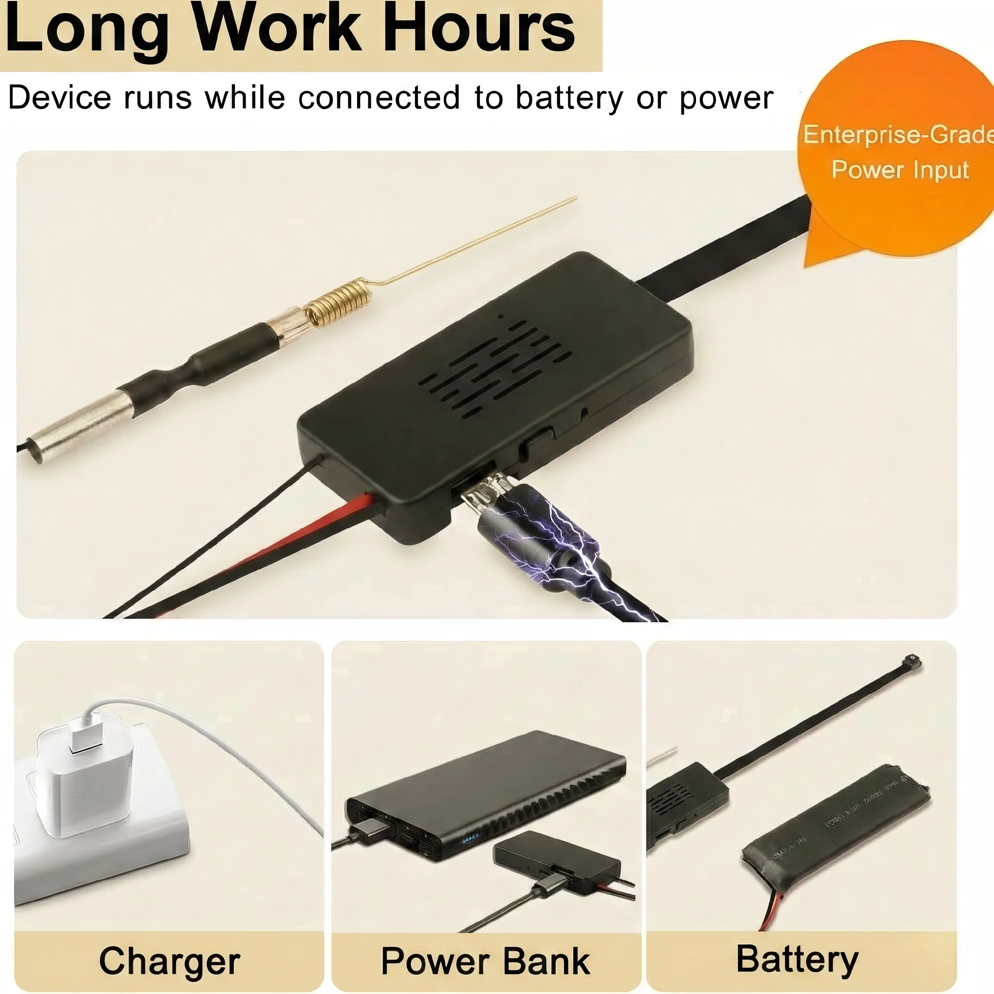
B2B clients frequently embed the C10 camera module inside a modified wall socket or power strip — combining the covert camera with a functioning power outlet. This is one of the highest-risk installation configurations for thermal failure.
The AC-DC step-down module required to convert 220V or 110V mains AC to 5V DC is itself a significant heat source. A typical miniature AC-DC isolated converter module (form factor: DIP or SMD, 24×16×12 mm) dissipates 1–3 W of heat at full load, with efficiency ranging from 75% to 85% depending on load and input voltage. At 220V input, the no-load power consumption alone generates 50–150 mW of heat continuously.
The failure mechanism when modules are stacked: If the AC-DC converter module is mounted directly adjacent to or on top of the C10 camera PCB — a natural mechanical choice when designing a compact dual-function socket — the converter’s thermal output adds directly to the camera module’s thermal environment. The combined heat load in a sealed ABS wall socket enclosure reaches 2–4 W, which in the thermal mass of a wall socket (typically 50–80 g of ABS plastic) raises the internal air temperature to 50–65°C above ambient within 20–30 minutes.
The required separation distance: The C10 module and the AC-DC converter must maintain a minimum of 15 mm of physical air gap in all three axes. This is not a recommendation — it is the minimum distance that allows the AC-DC converter’s heat to dissipate into the enclosure air before reaching the camera module’s inlet air. Stacking the modules directly, even with a thin metal shield between them, is insufficient because the shield acts as a thermal bridge rather than a barrier.
Mechanical layout guidance for wall socket installations:
1. Position the AC-DC converter at the bottom of the enclosure (farthest from the camera lens).
2. Use a metal partition plate between the converter and the camera module if space does not permit 15 mm air gap — the plate must not be mechanically bonded to both modules simultaneously; it should float on silicone thermal pads on both sides.
3. Drill 2–3 mm ventilation holes in the enclosure wall directly above the camera module to allow convection airflow. These holes are invisible from the front in most wall socket designs.
4. Do not seal the enclosure with silicone — leave the bottom edge unsealed by 0.5–1 mm to allow air exchange with the room.
Recording Strategy: Event-Based Mode Reduces Heat by 60%

The most effective software-level thermal mitigation strategy is reducing the module’s active processing time. Every second the ISP is encoding video, the SoC is processing WiFi frames, and the NAND is writing data — all three heat sources are simultaneously active. Reducing recording time proportionally reduces thermal load.
Modo de grabación continua 24/7: El módulo graba continuamente, codificando video H.264 a 1080p / 30fps. Disipación de potencia del SoC: aproximadamente 1.2 W sostenido. El equilibrio térmico en un recinto ABS sellado se alcanza aproximadamente a 55–70°C sobre la temperatura ambiente dentro de 60–90 minutos.
Grabación basada en eventos (detección de movimiento): El ISP entra en un modo de monitoreo de baja potencia entre eventos, codificando frames de previsualización aproximadamente a 1 fps mientras el algoritmo de detección de movimiento escanea la escena. Solo cuando se detecta movimiento el módulo cambia a codificación completa de 1080p / 30fps. En un entorno doméstico o de oficina típico, la grabación activada por movimiento produce 30–120 minutos de grabación real por período de 24 horas — una reducción de 80–90% en tiempo de codificación activa. La disipación de potencia del SoC promedio aproximadamente 400–500 mW en 24 horas. El equilibrio térmico en el mismo compartimento es aproximadamente 18–25°C superior al ambiente — dentro de los límites operativos seguros tanto para el SoC como para la microSD.
Para cambiar a grabación basada en eventos en la aplicación Tuya Smart / Smart Life:
1. Abra el dispositivo en la aplicación.
2. Pulse el icono de engranaje para acceder a Configuración.
3. Seleccione Plan de grabación or Configuración de almacenamiento.
4. Cambiar desde Grabación continua (24h) a Grabación de eventos or Detección de movimiento.
5. Ajuste el control de sensibilidad de detección de movimiento según el entorno — para interiores con mascotas, reduzca la sensibilidad para evitar eventos de grabación excesivos y generación continua de calor.
6. Confirme. El cambio se aplica inmediatamente sin reiniciar el módulo.
Para implementaciones B2B en entornos de alta seguridad donde se requiere cobertura 24/7, los pasos de gestión térmica en las secciones anteriores son obligatorios. Para vigilancia doméstica o de oficina de propósito general, la grabación basada en eventos elimina completamente el riesgo de fallo térmico.
Passive Ventilation Design for Custom Enclosures
Al integrar el módulo C10 en cualquier compartimento personalizado, la ventilación pasiva debe tratarse como un requisito de diseño de primera clase — no como una idea posterior.
El principio de convección: El aire caliente sube. En un compartimento cerrado, el aire más caliente se acumula en la parte superior, cerca de las fuentes de calor. Las perforaciones de ventilación en la parte superior del compartimento permiten que este aire caliente escape por convección natural, introduciendo aire más fresco del ambiente por las ventilaciones inferiores. El efecto neto es un cambio de aire continuo y de baja tasa que lleva el calor fuera de los componentes.
Patrón de ventilación recomendado para instalaciones del módulo C10:
1. Cortar 3–4 perforaciones de 2–3 mm de diámetro en la parte superior del compartimento, directamente sobre la ubicación del SoC en el PCB. Estas son las ventilaciones de escape.
2. Cortar 2–3 perforaciones de 2 mm de diámetro en la parte inferior del recinto, en la cara opuesta a la lente de la cámara. Estas son las ventilas de entrada.
3. No utilice agujeros más grandes — los agujeros más grandes reducen la integridad estructural y no mejoran significativamente el flujo de aire con la baja diferencia de presión creada por convección natural en un dispositivo pequeño.
4. Coloque el módulo de la cámara en la parte superior del dispositivo si es posible, con el SoC orientado hacia las salidas de ventilación.
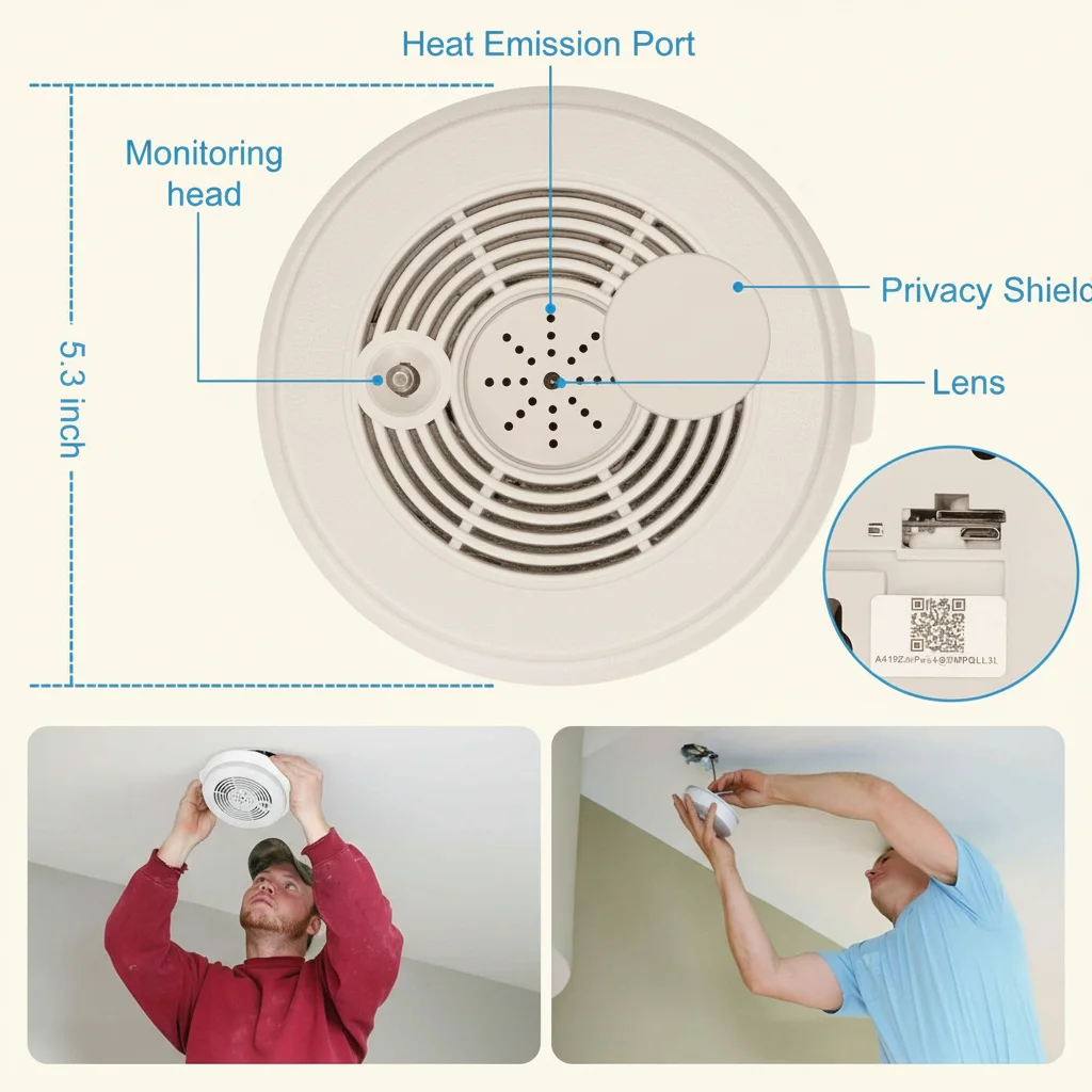
Para instalaciones en huecos del techo (por ejemplo, detrás de un detector de humo montado en el techo o una luminaria): El espacio sobre un panel de techo puede alcanzar 35–40°C en verano debido al calor que sube desde la habitación inferior y la insulación superior. Si el módulo C10 se instala en dicho espacio, los pasos de gestión térmica anteriores son especialmente críticos. Considere dirigir la antena WiFi fuera del espacio mediante un glande de cable hacia un lugar con mejor entorno térmico — la posición de la antena no tiene impacto térmico y el glande de cable proporciona un paso sellado que mantiene la apariencia de la habitación.
Diagnóstico de Sobrecalentamiento: Identificación de Fallos Térmicos frente a Otros Problemas
No todos los fallos son un problema térmico. Aquí se explica cómo identificar si un fallo del módulo C10 es causado térmicamente:
| Síntoma | Causa térmica | Otro probable motivo | Acción diagnóstica |
|---|---|---|---|
| El dispositivo se desconecta después de 1-2 horas | Limitación térmica a ~85°C de unión | Direccionamiento AP del router WiFi | Observe si la falla se correlaciona con la temperatura ambiente o la duración de la grabación continua |
| La tarjeta SD se vuelve ilegible después de un período de calor | Tarjeta sobrecalentada (>70°C) | Fallos de tarjeta / corrupción FAT | Retirar la tarjeta, probar en PC; probar la tarjeta en otro dispositivo a temperatura ambiente |
| El dispositivo se reinicia sin aviso | Reinicio térmico fuerte (>110°C máximo absoluto) | Fallo del firmware | Si el dispositivo se reinicia siempre después de la misma duración, es térmico; si el momento varía aleatoriamente, es software |
| La grabación se detiene pero la aplicación aún muestra la vista en vivo | Apagado térmico ISP / NAND | Almacenamiento completo / error de firmware | Verifique el almacenamiento disponible en la aplicación; observe si la vista en vivo continúa después de que la grabación se detiene (lo hace en el apagado térmico de la NAND) |
| El dispositivo funciona bien durante días y luego falla repentinamente | Degradación térmica gradual de la interfaz térmica | Fallo aleatorio del firmware | El momento del fallo en la degradación térmica es predecible y reproducible; un momento aleatorio sugiere software |
Preguntas frecuentes
P: Mi módulo está dentro de una carcasa de aluminio. ¿Necesito aún una almohadilla térmica?
R: Sí, pero el enfoque cambia. Las carcasas de aluminio conducen el calor eficientemente, pero la resistencia térmica en la interfaz entre la PCB y el aluminio sigue siendo significativa sin TIM. Aplique la almohadilla térmica al SoC como se describe, luego use compuesto térmico (Arctic MX-4 o equivalente, aplicado en una capa fina) en la interfaz entre la PCB y la pared de aluminio. El aluminio actuará como un difusor, distribuyendo el calor por su superficie y luego disipándolo al aire ambiente. En carcasas de aluminio, una reducción de 8–12°C es típica comparada con la misma carcasa sin gestión térmica.
P: ¿Puedo usar un pequeño ventilador para enfriar el módulo?
R: Un pequeño ventilador DC brushless de 5V (20×20×5 mm, disponible en proveedores de electrónica) puede reducir la temperatura interna del aire entre 15–25°C y elimina completamente la limitación térmica en casi todos los escenarios de carcasa sellada. Conecte el ventilador a los rails de 5V y GND de la entrada USB del módulo C10. El consumo de corriente de un ventilador de 5V 20mm (60–120 mA) está dentro del estándar USB de 500 mA. Coloque el ventilador para que sople sobre el SoC y la tarjeta SD — no para que sople hacia la lente. El compromiso es el ruido audible: los ventiladores a máxima velocidad suelen ser de 18–28 dB, audibles en habitaciones silenciosas pero aceptables para cuartos de servicio y oficinas.
P: ¿A qué temperatura falla realmente la tarjeta microSD?
R: Las tarjetas microSD de grado comercial (la gran mayoría de las tarjetas vendidas) están clasificadas para operación entre 0°C y 70°C. El inicio del fallo generalmente comienza a 65°C con incrementos de reintentos de lectura, y se vuelve catastrófico (tarjeta no responde) arriba de 72°C. Las tarjetas de grado industrial (-25°C a 85°C) son significativamente más resistentes pero añaden $8–15 por tarjeta. Para la mayoría de las implementaciones B2B en ambientes con clima controlado, la gestión térmica de la carcasa es la solución más rentable que especificar almacenamiento de grado industrial.
P: Estamos instalando 200 unidades en un edificio comercial. ¿Cuál es la lista de verificación de puesta en servicio?
A: Para implementaciones a gran escala: (1) Especificar tarjetas microSD de grado industrial (o aceptar una tasa de falla anual de tarjetas de 2–3% con tarjetas comerciales en ambientes sin AC). (2) Requerir grabación basada en eventos como la configuración de firmware predeterminada. (3) Requerir que cada instalación incluya una almohadilla térmica y un camino térmico documentado hacia el material de la carcasa. (4) Comisionar una muestra de 10 unidades con una medición de termocupla dentro de la carcasa en la temperatura máxima de operación (operar 2 horas, medir con una sonda de termocupla tipo K insertada por un orificio de ventilación). (5) Establecer un umbral de alerta del firmware: si el módulo se reinicia más de una vez por período de 7 días, activar una inspección de mantenimiento.
P: El módulo funciona bien durante el día pero falla en la noche. ¿Qué está ocurriendo?
A: Esta es una firma térmica clásica. Durante el día, el HVAC del edificio está funcionando y la temperatura ambiente de la habitación puede ser de 22–24°C. En la noche cuando el HVAC se apaga, la temperatura de la habitación aumenta a 26–30°C — y en espacios cerrados con ventilación deficiente, la temperatura interna de la carcasa aumenta aún más por 15–20°C. El umbral de temperatura de falla nocturna se alcanza aproximadamente 2–4 horas después del apagado del HVAC. Cambiar a grabación basada en eventos soluciona esto sin modificación del hardware.
Conclusión
La falla térmica en módulos de cámara basados en C10 es un problema de diseño e instalación, no un defecto del componente. El SoC RTL8710BN y la tarjeta microSD son capaces de operar confiablemente a temperaturas elevadas — siempre que el calor sea conducido fuera del módulo y disipado al entorno.
Los tres requisitos obligatorios para una instalación confiable a largo plazo son: primero, no envolver el módulo en material aislante; aplicar siempre una almohadilla térmica con un camino conductor hacia la carcasa. Segundo, mantener una separación física entre el módulo C10 y cualquier componente de conversión de potencia AC-DC — una separación de aire mínima de 15 mm, o una partición metálica flotante con TIM en ambos lados. Tercero, cambiar de la grabación continua 24/7 a la grabación basada en eventos de detección de movimiento donde sea posible — este único cambio en el software reduce la carga térmica promedio entre 60–80%.
Para clientes B2B que integran el módulo C10 a gran escala, la gestión térmica debe tratarse como un requisito de diseño desde el primer día, no como un ejercicio de solución de problemas posterior a la implementación. Una almohadilla térmica de 15 centavos y dos orificios de ventilación cuestan menos que una sola devolución por garantía.

 English
  Italiano
  Deutsch
  Français
  Español
  Polski