
How to Fix Overheating in Tuya C10 Camera Modules
When a Tuya C10-based camera module drops offline after two hours of operation, resets itself without warning, or corrupts a microSD card at high ambient temperature — the root cause is almost always the same: thermal failure, not hardware defect. The symptoms are predictable and reproducible because they follow the thermal behavior of the onboard DSP and wireless chipset at elevated junction temperatures.
This guide covers the thermal design principles that govern C10 module operation, explains why certain installation environments cause failures, and provides specific mitigation steps for each failure mode. For OEM integrators and B2B clients who are embedding these modules into third-party enclosures, this is the documentation that the product datasheet does not include.
How Heat Is Generated Inside a C10 Camera Module
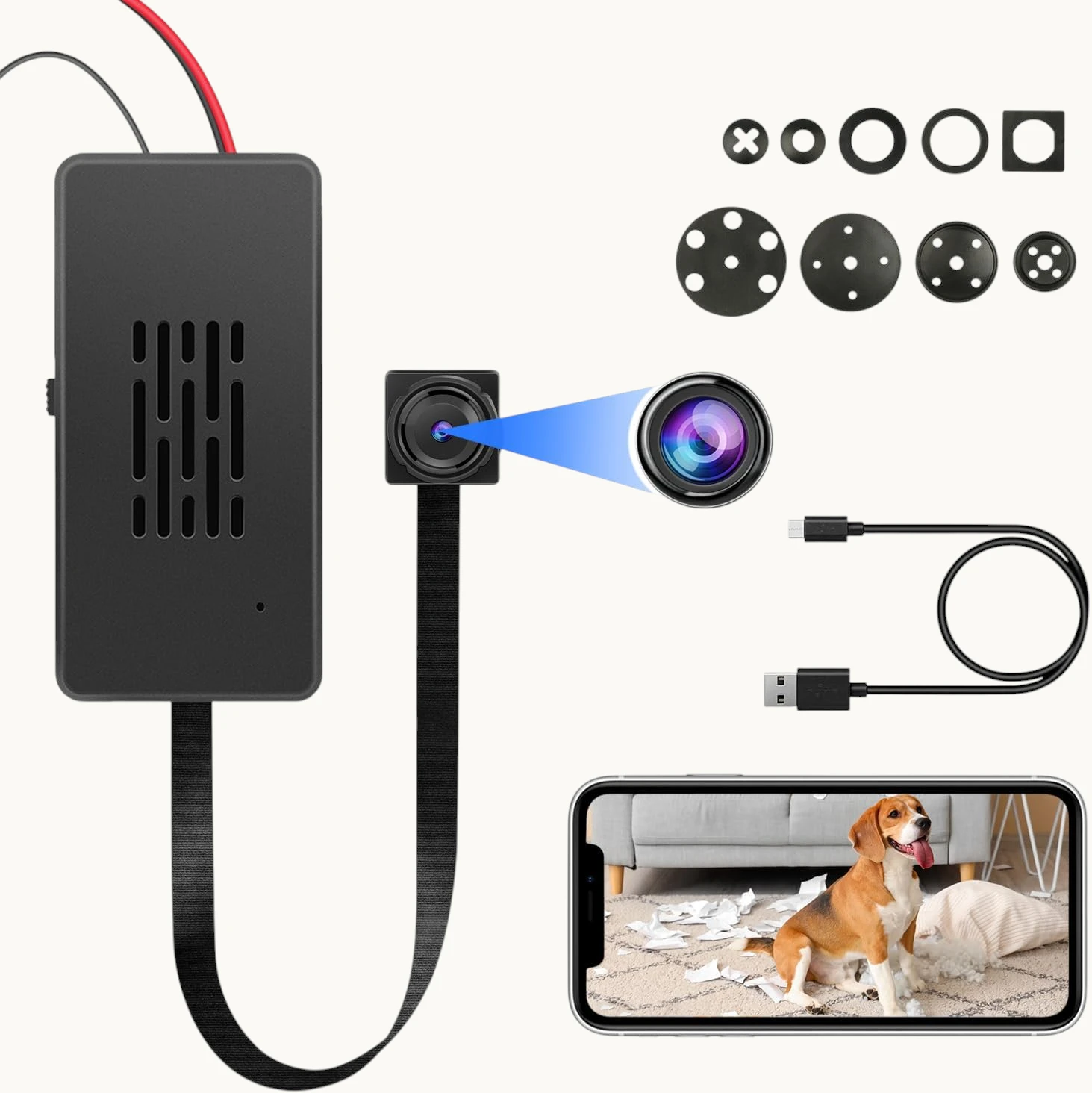
The C10 module contains three primary heat-generating components, each with a distinct thermal signature:
RTL8710BN WiFi SoC (primary heat source). This is the dominant heat source on the module. The RTL8710BN integrates a 125 MHz ARM Cortex-M4F CPU with a full 802.11 b/g/n MAC and baseband processor. Under active P2P streaming or heavy WiFi traffic, the SoC dissipates between 350 mW and 700 mW depending on transmit power and data rate. In still air at room temperature, the die temperature rise above ambient (theta-JA) for the QFN-48 package is approximately 80°C/W — meaning at 500 mW dissipation, the die temperature rises 40°C above the local air temperature.
Camera ISP (Image Signal Processor). The OV9734 or equivalent image sensor includes an onboard ISP that performs demosaicing, noise reduction, and exposure correction at 30 fps. ISP power consumption is relatively constant during active recording, adding approximately 150–250 mW to the thermal load regardless of scene complexity.
Power management ICs (LDOs and DC-DC converters). The 3.3 V and 1.8 V rails are generated from the 5 V USB input through a combination of low-dropout regulators and a single-channel buck converter. LDO regulators dissipate (Vin – Vout) × Iload as heat — at typical operating current (400–500 mA total), the LDO stages collectively dissipate 300–600 mW even at high efficiency.
Total dissipation in active-recording mode: approximately 1.0–1.5 W. In a sealed plastic enclosure with no thermal path to ambient air, this heat accumulates. The internal air temperature rises until the rate of heat generation equals the rate of heat dissipation through the enclosure walls — a steady-state equilibrium that for a small 50×50×30 mm enclosure in still indoor air typically reaches 35–45°C above ambient.
At 25°C room temperature, the internal equilibrium reaches 60–70°C. At 30°C (summer conditions, enclosed ceiling void), it reaches 65–75°C. At these temperatures, the thermal runaway threshold for the RTL8710BN is not yet reached — but the microSD card, which is designed for commercial-grade temperature ranges (0°C to 70°C for standard cards), begins to experience intermittent failures.
Why Sealed Enclosures and Insulation Wrapping Cause Failures
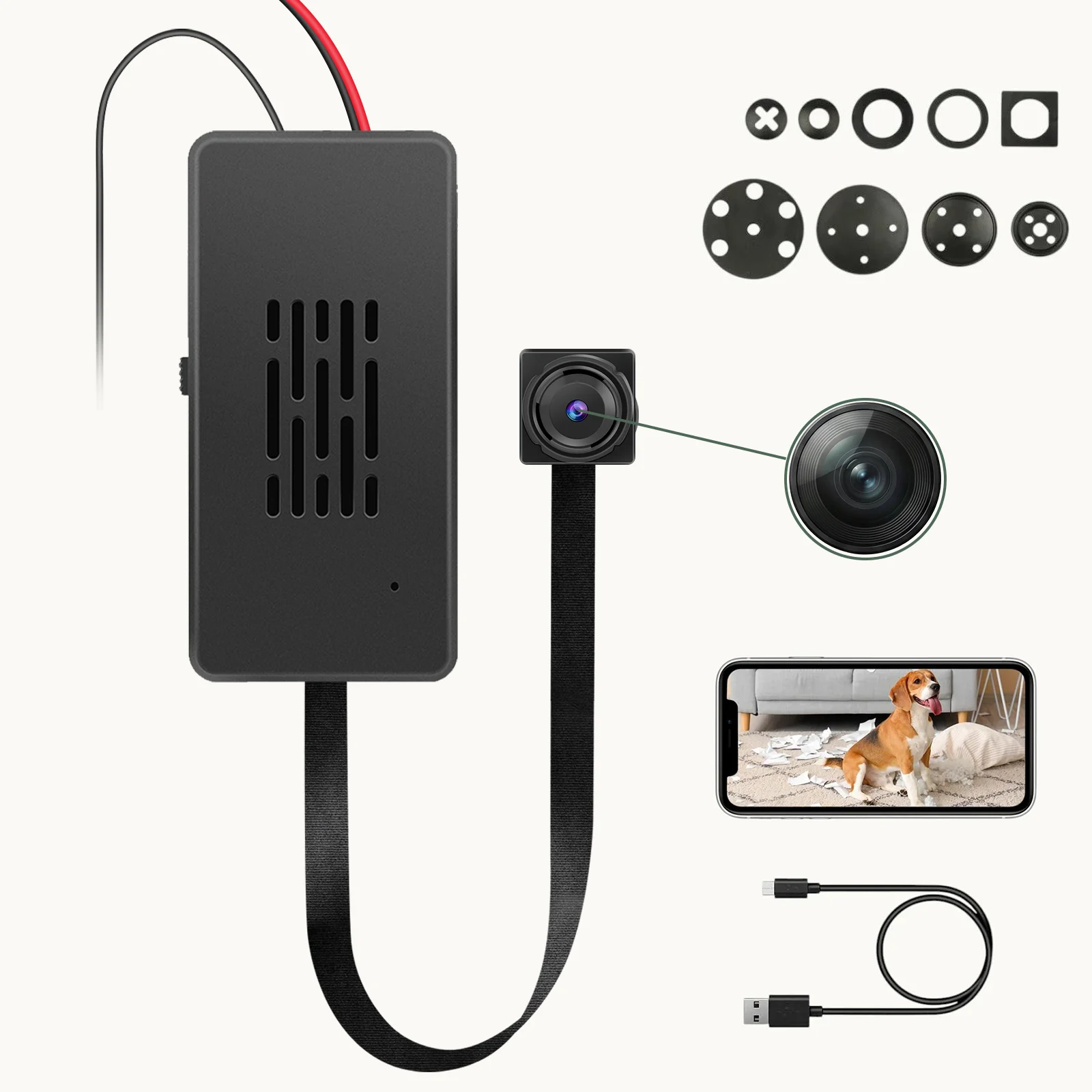
The most common integration mistake made by B2B clients is wrapping the module in electrical insulation tape or enclosing it in a sealed box without ventilation — usually motivated by the desire to make the installation appear clean and professional.
Electrical tape is a thermal insulator. It has a thermal conductivity of approximately 0.2 W/m·K, compared to air (0.026 W/m·K) and aluminum (237 W/m·K). Wrapping the module in tape adds a thin but thermally significant boundary layer between the components and the surrounding air, trapping heat directly against the PCB surface. The heat generated by the SoC cannot escape through this barrier and accumulates on the component-side of the board, raising the temperature of every component within 5 mm of the heat source.
What the thermal imaging actually shows: In a wrapped installation, the SoC temperature reaches the thermal throttling threshold (typically 85°C junction temperature) within 30–45 minutes of continuous operation. The RTL8710BN’s built-in thermal management kicks in: the ARM core reduces its clock frequency from 125 MHz to 62.5 MHz, then to 31.25 MHz in staged steps. At 62.5 MHz, the WiFi MAC processing throughput drops below the threshold required to maintain a stable P2P connection — the module drops offline in the app. If the temperature continues to rise, the chip performs a hard reset to protect the die.
The microSD card secondary failure: Standard microSD cards are rated for operation from 0°C to 70°C commercial temperature range. Cards used in the -25°C to 85°C extended temperature range (industrial grade) cost 3–5× more per unit. At sustained internal temperatures above 65°C, the card’s internal NAND controller firmware begins to exhibit read-retry cycles, ECC failure rate increases, and eventually the card stops responding to commands. In FAT32 filesystem environments, this manifests as “card error,” “card full,” or the inability to write new files — even when the card appears to be empty when mounted on a PC.
Thermal Pad Application: The Correct Method
The correct thermal management approach for C10 module installations uses thermal interface material (TIM) to create a conduction path from the module to the enclosure:
Select the correct thermal pad. The SoC on the C10 module is exposed on the component side — there is no dedicated thermal pad pre-applied. Apply a 1.5 mm thick silicone thermal pad with thermal conductivity of 3–5 W/m·K (commonly rated as “3W/mK” or “5W/mK” thermal pad, available from electronics suppliers). Thinner pads (<1 mm) compress excessively under enclosure pressure and lose thermal contact. thicker pads (>2 mm) increase thermal resistance beyond what the module can tolerate.
Placement procedure:
1. Power off the module and disconnect all cables.
2. Clean the top surface of the RTL8710BN chip and surrounding components with a dry lint-free cloth. Do not use isopropyl alcohol — it can dissolve the chip marking ink and does not affect thermal performance.
3. Place the thermal pad directly on top of the chip and surrounding area, ensuring full coverage of the SoC and power management ICs. The pad should not extend to the edges of the PCB in a way that creates a risk of shorting any exposed component leads.
4. Route the thermal path: position the module inside the enclosure so that the thermal pad contacts the inner surface of the enclosure wall. The ideal enclosure material is aluminum or steel (high thermal conductivity). ABS plastic is less effective but acceptable if the contact area is large (>15×15 mm).
5. Mechanical retention: ensure the enclosure provides consistent pressure on the thermal pad — the pad must not shift during shipping or handling. Foam tape on the enclosure interior behind the module provides consistent compression.
For plastic-only enclosures with no metallic thermal path: Apply the thermal pad to the SoC and any nearby power ICs, then route it to a flat area of the ABS enclosure with the largest surface area. ABS has a thermal conductivity of approximately 0.3 W/m·K — slow, but with sufficient surface area contact to ambient air, passive dissipation is possible. In a 80×80×50 mm ABS enclosure with a 15×15 mm thermal pad contacting a flat interior wall, the achievable steady-state temperature reduction is approximately 8–12°C compared to no thermal management at all.
Power Supply Separation: The 220V/110V AC-DC Brick Problem
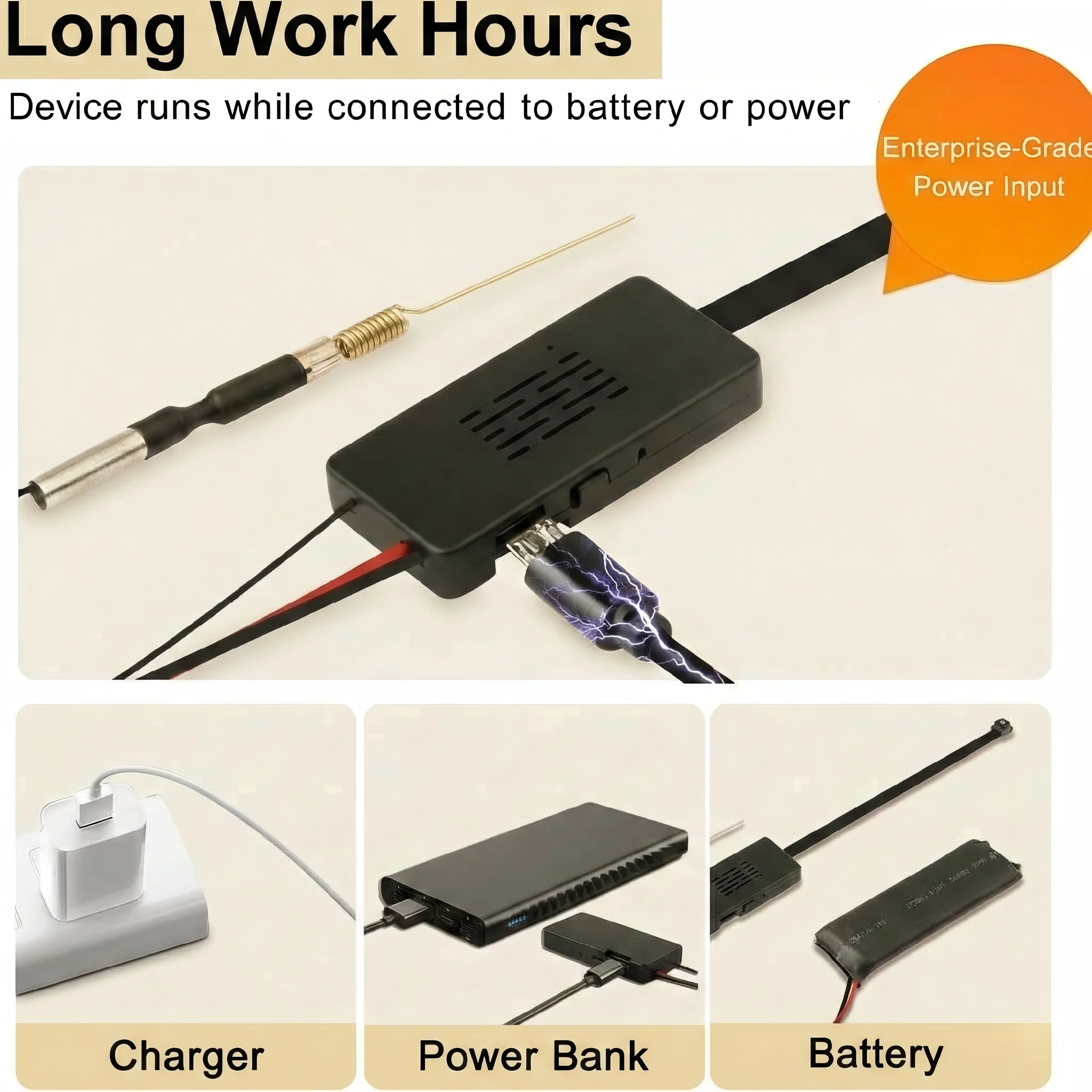
B2B clients frequently embed the C10 camera module inside a modified wall socket or power strip — combining the covert camera with a functioning power outlet. This is one of the highest-risk installation configurations for thermal failure.
The AC-DC step-down module required to convert 220V or 110V mains AC to 5V DC is itself a significant heat source. A typical miniature AC-DC isolated converter module (form factor: DIP or SMD, 24×16×12 mm) dissipates 1–3 W of heat at full load, with efficiency ranging from 75% to 85% depending on load and input voltage. At 220V input, the no-load power consumption alone generates 50–150 mW of heat continuously.
The failure mechanism when modules are stacked: If the AC-DC converter module is mounted directly adjacent to or on top of the C10 camera PCB — a natural mechanical choice when designing a compact dual-function socket — the converter’s thermal output adds directly to the camera module’s thermal environment. The combined heat load in a sealed ABS wall socket enclosure reaches 2–4 W, which in the thermal mass of a wall socket (typically 50–80 g of ABS plastic) raises the internal air temperature to 50–65°C above ambient within 20–30 minutes.
The required separation distance: The C10 module and the AC-DC converter must maintain a minimum of 15 mm of physical air gap in all three axes. This is not a recommendation — it is the minimum distance that allows the AC-DC converter’s heat to dissipate into the enclosure air before reaching the camera module’s inlet air. Stacking the modules directly, even with a thin metal shield between them, is insufficient because the shield acts as a thermal bridge rather than a barrier.
Mechanical layout guidance for wall socket installations:
1. Position the AC-DC converter at the bottom of the enclosure (farthest from the camera lens).
2. Use a metal partition plate between the converter and the camera module if space does not permit 15 mm air gap — the plate must not be mechanically bonded to both modules simultaneously; it should float on silicone thermal pads on both sides.
3. Drill 2–3 mm ventilation holes in the enclosure wall directly above the camera module to allow convection airflow. These holes are invisible from the front in most wall socket designs.
4. Do not seal the enclosure with silicone — leave the bottom edge unsealed by 0.5–1 mm to allow air exchange with the room.
Recording Strategy: Event-Based Mode Reduces Heat by 60%

The most effective software-level thermal mitigation strategy is reducing the module’s active processing time. Every second the ISP is encoding video, the SoC is processing WiFi frames, and the NAND is writing data — all three heat sources are simultaneously active. Reducing recording time proportionally reduces thermal load.
24/7 kontinuierlicher Aufnahmemodus: Das Modul zeichnet kontinuierlich H.264-Video mit 1080p / 30fps auf. SoC-Leistungsabgabe: etwa 1,2 W im Dauermodus. Das thermische Gleichgewicht in einem geschlossenen ABS-Gehäuse wird nach etwa 60–90 Minuten bei etwa 55–70°C über der Umgebungstemperatur erreicht.
Ereignisbasierte Aufzeichnung (Bewegungserkennung): Der ISP geht zwischen Ereignissen in einen Low-Power-Monitoring-Modus, kodiert Preview-Frames bei etwa 1 fps während der Bewegungserkennungsalgorithmus die Szene scannt. Nur wenn Bewegung erkannt wird, schaltet das Modul auf vollständige 1080p / 30fps Kodierung. In einer typischen häuslichen oder Büroumgebung produziert bewegungsgesteuerte Aufnahme 30–120 Minuten tatsächlicher Aufnahme pro 24-Stunden-Periode – eine 80–90% Reduktion der aktiven Kodierungszeit. SoC-Leistungsabgabe liegt über 24 Stunden bei etwa 400–500 mW. Das thermische Gleichgewicht im gleichen Gehäuse liegt etwa 18–25°C über Umgebung – gut innerhalb der sicheren Betriebsgrenzen für sowohl SoC als auch microSD-Karte.
Um zur ereignisbasierten Aufnahme in der Tuya Smart / Smart Life App zu wechseln:
1. Öffnen Sie das Gerät in der App.
2. Tippen Sie auf das Zahnradsymbol, um die Einstellungen zu öffnen.
3. Wählen Sie Aufzeichnungsplan oder Speicher-Einstellungen.
4. Ändern von Kontinuierliche Aufnahme (24h) zu Ereignisaufzeichnung oder Bewegungserkennung.
5. Passen Sie den Bewegungserkennungsempfindlichkeitsschieber an die Umgebung an – für Indoor-Umgebungen mit Haustieren reduzieren Sie die Empfindlichkeit, um übermäßige Aufnahmeereignisse und fortlaufende Wärmeentwicklung zu vermeiden.
6. Bestätigen. Die Änderung wird ohne Modulneustart direkt wirksam.
Für B2B-Installationen in Hochsicherheitsumgebungen mit 24/7-Abdeckung sind die thermischen Management-Schritte der vorherigen Abschnitte obligatorisch. Für allgemeine Heim- oder Büroüberwachung eliminiert ereignisbasierte Aufnahme das thermische Fehlerrisiko vollständig.
Passive Ventilation Design for Custom Enclosures
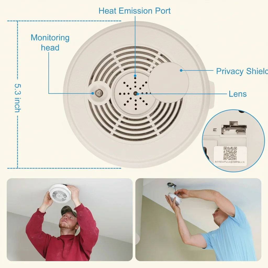
Bei der Integration des C10-Moduls in ein individuelles Gehäuse sollte passive Ventilation als primäre Designanforderung behandelt werden – nicht als nachträgliche Ergänzung.
Das Konvektionsprinzip: Heiße Luft steigt auf. In einem geschlossenen Gehäuse sammelt sich die heißeste Luft oben, nahe den Wärmequellen. Ventilationsöffnungen am oberen Ende des Gehäuses ermöglichen, dass diese heiße Luft durch natürliche Konvektion entweicht und kühler Raumluft durch Bodenöffnungen einzieht. Der Nettoeffekt ist eine kontinuierliche Luftwechselrate, die Wärme von den Komponenten abtransportiert.
Empfohlenes Belüftungsmuster für C10-Modul-Installationen:
1. Schneiden 3–4 Löcher mit 2–3 mm Durchmesser Am oberen Ende des Gehäuses, direkt über der SoC-Position auf der PCB. Dies sind die Auslassöffnungen.
2. Schneiden 2–3 Löcher mit 2 mm Durchmesser am Boden des Gehäuses, auf der gegenüberliegenden Seite der Kameraoptik. Dies sind die Einlassöffnungen.
3. Verwenden Sie keine größeren Löcher – größere Löcher reduzieren die strukturelle Integrität und verbessern den Luftstrom bei dem geringen Druckunterschied durch natürliche Konvektion in einem kleinen Gehäuse nicht signifikant.
4. Positionieren Sie das Kameramodul möglichst oben im Gehäuse, mit dem SoC Richtung der Auslassöffnungen.
Für Installationen in Deckenhohlräumen (z.B. hinter einem deckenmontierten Rauchmelder oder Leuchtmittel): Der Hohlraum über einer Deckenplatte kann im Sommer 35–40°C erreichen, aufgrund von aufsteigender Hitze aus dem Raum unten und Isolierung oben. Wenn das C10-Modul in einem solchen Hohlraum installiert ist, sind die thermischen Management-Schritte oben besonders kritisch. Erwägen Sie, die WiFi-Antenne durch eine Kabelverschraubung aus dem Hohlraum an einen Ort mit besserer thermischer Umgebung zu führen – die Antennenposition hat keinen thermischen Einfluss und die Kabelverschraubung bietet einen geschlossenen Durchgang, der das Raumbild bewahrt.
Überhitzungsdiagnose: Identifizierung von thermischen Ausfällen im Vergleich zu anderen Problemen
Nicht jeder Fehler ist ein thermisches Problem. Hier erfahren Sie, wie Sie feststellen können, ob ein C10-Modulfehler thermisch verursacht ist:
| Symptom | Thermische Ursache | Andere wahrscheinliche Ursache | Diagnostische Maßnahme |
|---|---|---|---|
| Gerät geht nach 1–2 Stunden offline | Thermische Drosselung bei ~85°C Junction | WiFi-Router AP Steering | Beobachten, ob der Fehler mit Raumtemperatur oder Dauer der kontinuierlichen Aufnahme korreliert |
| SD-Karte wird nach einer heißen Phase unlesbar | Kartenüberhitzung (>70°C) | Kartenfehler / FAT-Korruption | Karte entfernen, auf PC testen; Karte in einem anderen Gerät bei Raumtemperatur testen |
| Gerät startet ohne Warnung neu | Thermischer Hard Reset (>110°C absolute Maximaltemperatur) | Firmware-Absturz | Wenn das Gerät jedes Mal nach der gleichen Zeitdauer neu startet, ist es thermisch; wenn die Zeit variiert, ist es softwarebedingt |
| Aufnahme stoppt, aber App zeigt noch Live-Ansicht | ISP / NAND thermische Abschaltung | Speicher voll / Firmware-Bug | Überprüfen Sie den verfügbaren Speicherplatz in der App; beobachten Sie, ob die Live-Ansicht nach Aufnahmeende weiterläuft (bei thermischem NAND-Shutdown ist dies der Fall) |
| Gerät läuft tagelang einwandfrei und fällt dann plötzlich aus | Graduelle thermische Degradation der thermischen Schnittstelle | Zufälliger Firmware-Ausfall | Der Zeitpunkt des Ausfalls bei thermischer Degradation ist vorhersehbar und reproduzierbar; ein zufälliger Zeitpunkt deutet auf Software hin. |
Häufig gestellte Fragen
F: Mein Modul befindet sich in einer Aluminiumgehäuse. Brauche ich noch eine thermische Unterlage?
A: Ja, aber der Ansatz ändert sich. Aluminiumgehäuse leiten Wärme effizient ab, aber der thermische Widerstand an der Schnittstelle zwischen PCB und Aluminium ist ohne TIM (Thermal Interface Material) noch signifikant. Trage das Thermalpad auf den SoC wie beschrieben auf und verwende dann thermische Paste (Arctic MX-4 oder gleichwertig, als dünne Schicht aufgetragen) an der Schnittstelle zwischen PCB und Aluminiumwand. Das Aluminium fungiert als Wärmespreizer, verteilt die Wärme über seine Oberfläche und gibt sie dann an die Umgebungsluft ab. In Aluminiumgehäusen ist eine Reduktion von 8–12°C typisch im Vergleich zum gleichen Gehäuse ohne thermische Verwaltung.
Q: Kann ich einen kleinen Lüfter zur Kühlung des Moduls verwenden?
A: Ein kleiner 5V DC bürstenloser Lüfter (20×20×5 mm, verfügbar bei Elektroniklieferanten) kann die interne Lufttemperatur um 15–25°C reduzieren und thermische Drosselung in fast allen geschlossenen Gehäusen vollständig eliminieren. Verbinde den Lüfter mit den 5V und GND Leitungen des USB-Eingangs des C10-Moduls. Der Stromverbrauch eines 5V 20mm Lüfters (60–120 mA) liegt deutlich innerhalb des 500 mA USB-Standards. Positioniere den Lüfter, so dass er über den SoC und die SD-Karte bläst – nicht in die Linse. Der Nachteil ist Geräuschentwicklung: Lüfter auf voller Geschwindigkeit sind typisch 18–28 dB, in stillen Räumen hörbar, aber für Nebenräume und Büros akzeptabel.
Q: Bei welcher Temperatur versagt die microSD-Karte eigentlich?
A: Kommerzielle microSD-Karten (die große Mehrheit der verkauften Karten) sind für den Betrieb von 0°C bis 70°C ausgelegt. Fehlerbeginn beginnt typisch bei 65°C mit erhöhten Lesewiederholungen und wird katastrophal (Karte reagiert nicht) über 72°C. Industrielle Karten (-25°C bis 85°C) sind deutlich widerstandsfähiger, aber kosten $8–15 zusätzlich pro Karte. Für die meisten B2B-Installationen in klimakontrollierten Umgebungen ist die thermische Management des Gehäuses die kosteneffektivere Lösung, statt industrielle Speichermedien zu spezifizieren.
Q: Wir installieren 200 Einheiten in einem kommerziellen Gebäude. Was ist die Inbetriebnahmeprüfliste?
A: Für großflächige Installationen: (1) Industrielle microSD-Karten spezifizieren (oder eine 2–3% jährliche Kartenausfallrate mit kommerziellen Karten in Nicht-AC-Umgebungen akzeptieren). (2) Ereignisbasierte Aufzeichnung als Standard-Firmwarekonfiguration festlegen. (3) Jede Installation muss ein Thermalpad und dokumentierten thermischen Weg zum Gehäusematerial enthalten. (4) Eine Stichprobe von 10 Einheiten mit Thermoelementmessung innerhalb des Gehäuses bei maximaler Betriebstemperatur beauftragen (2 Stunden laufen, Messung mit einem K-Typ Thermoelement-Sonde durch eine Lüftungsöffnung). (5) Eine Firmware-Alarmgrenze setzen: Wenn das Modul mehr als einmal pro 7-Tage-Periode neu startet, eine Wartungsinspektion auslösen.
Q: Das Modul funktioniert tagsüber gut, aber versagt am Abend. Was passiert?
A: Dies ist eine klassische thermische Signatur. Tagsüber läuft die Gebäude-HVAC und die Raumtemperatur kann 22–24°C sein. Am Abend, wenn die HVAC abgeschaltet wird, steigt die Raumtemperatur auf 26–30°C – und in geschlossenen Räumen mit schlechter Belüftung steigt die interne Gehäusetemperatur um weitere 15–20°C. Die Ausfalltemperaturgrenze am Abend wird etwa 2–4 Stunden nach HVAC-Abschaltung erreicht. Der Wechsel zu ereignisbasierter Aufzeichnung lösen dies ohne Hardwareänderung.
Schlussfolgerung
Thermischer Ausfall in C10-basierten Kamera-Modulen ist ein Design- und Installationsproblem, nicht ein Komponentendefekt. Der RTL8710BN SoC und die microSD-Karte sind für einen zuverlässigen Betrieb bei erhöhten Temperaturen geeignet – vorausgesetzt, dass die Wärme vom Modul abgeleitet und in die Umgebung abgeführt wird.
Die drei obligatorischen Anforderungen für eine zuverlässige Langzeitinstallation sind: erstens, das Modul nicht in isolierenden Material umwickeln; immer eine thermische Unterlage mit einem leitenden Weg zum Gehäuse anbringen. Zweitens, physikalische Trennung zwischen dem C10-Modul und allen AC-DC Stromwandlungskomponenten halten – mindestens 15 mm Luftspalt, oder eine freistehende Metallabtrennung mit TIM auf beiden Seiten. Drittens, von kontinuierlicher 24/7 Aufzeichnung zu ereignisbasierter Bewegungserkennungsaufzeichnung umschalten, wo möglich – diese einzelne Softwareänderung reduziert die thermische Belastung um 60–80%.
Für B2B-Kunden, die das C10-Modul in großem Umfang integrieren, sollte die thermische Verwaltung als eine Design-Anforderung vom ersten Tag behandelt werden, nicht als eine Fehlerbehebungsmaßnahme nach der Installation. Ein 15-Cent-Thermalpad und zwei Lüftungsöffnungen kosten weniger als eine einzige Garantierückgabe.

 English
  Italiano
  Deutsch
  Français
  Español
  Polski