
Jak obudzić długo przechowywaną baterię kamery szpiegowskiej
If your spy camera, voice recorder, or covert recording device has been sitting in a warehouse shelf for three months or longer, and it now refuses to power on, shows no LED indicator, and does not respond to any button press — the device is almost certainly not dead. It is in over-discharge protection lockout, a built-in safety mechanism that has shut down the battery to prevent permanent damage.
This guide explains why the lockout occurs, how the Battery Management System (BMS) enforces it at the hardware level, and exactly how to safely wake the device up using trickle charging. It also covers the maintenance protocol that warehouse distributors and B2B resellers should follow to prevent this issue across their inventory.
Why Your Battery Enters Protection Lockout: The BMS Mechanism
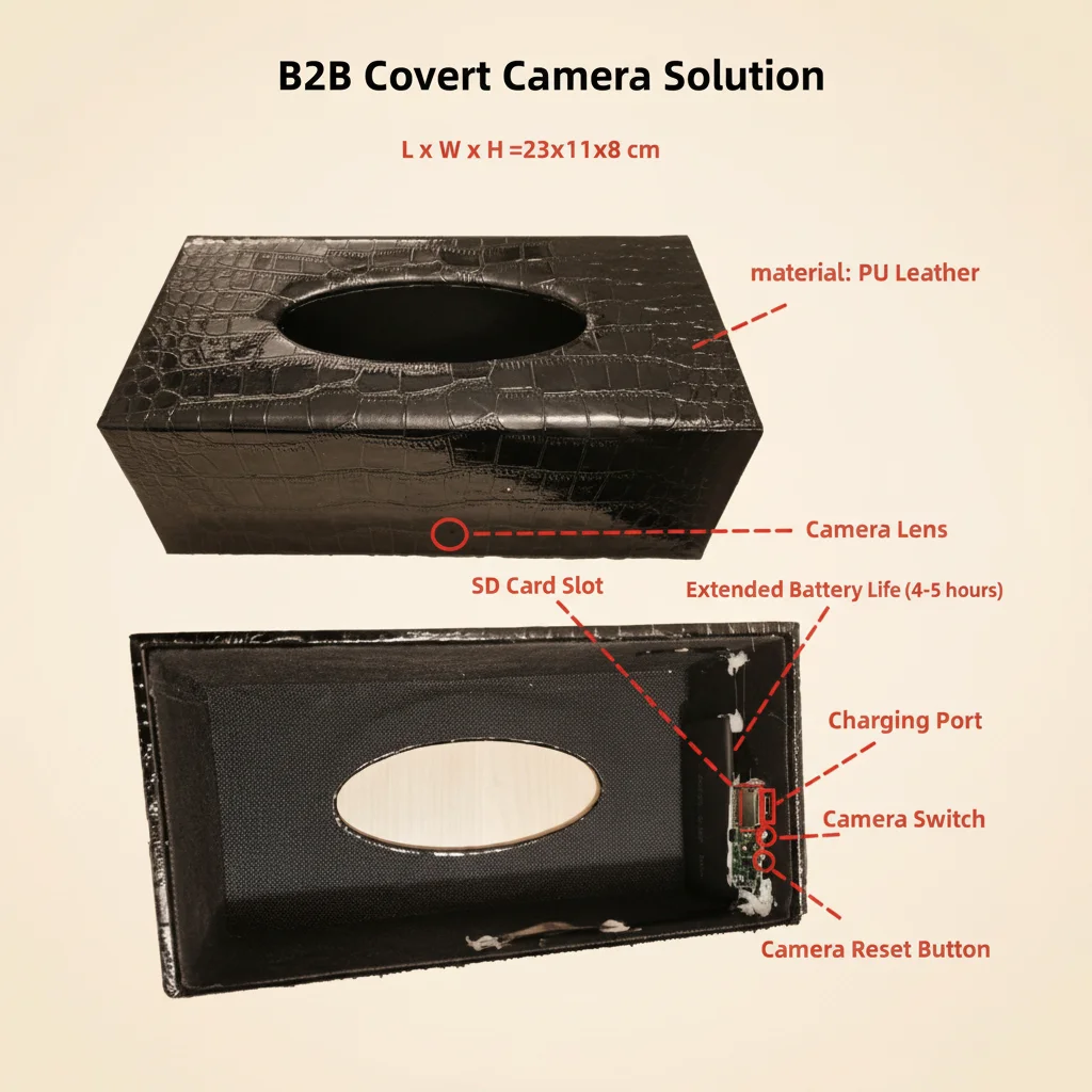
All lithium polymer (LiPo) and lithium-ion (Li-ion) cells used in QZT covert recording devices carry a hardware-level Battery Management System — a dedicated protection IC embedded on the device’s power board. This is not firmware or software: it is a physical circuit that responds to voltage thresholds faster than any operating system can intervene.
The BMS enforces three hard cutoffs to prevent hazardous conditions:
Over-discharge cutoff (the lockout you are experiencing). When the cell voltage falls below 3.2 V during a storage period, the protection MOSFET disconnects the negative terminal from the rest of the circuit. The device cannot draw any current — even in standby. This cutoff activates at approximately 70% state-of-charge for a typical 3.7 V LiPo cell, which means a device left at 50% charge and stored for 4–6 months without a maintenance top-up cycle will reliably trigger this protection.
Over-charge cutoff. If a cell reaches 4.25 V during charging, the BMS cuts the charge path to prevent thermal runaway. QZT devices incorporate this protection so that using any compliant 5 V USB power source is safe, even if the charger behaves unexpectedly.
Short-circuit and over-current cutoff. Any current draw exceeding approximately 3 A for more than 10 ms triggers an immediate disconnection. High-power fast chargers (PD, QC) can produce inrush current spikes during initial connection negotiation that exceed this threshold, causing the BMS to enter a secondary lockout on top of the existing over-discharge lockout — making the device significantly harder to recover.
The over-discharge lockout is the most common cause of “dead on arrival” reports from distributors who store inventory without active power management. It is not a defect; it is the BMS doing exactly what it was designed to do.
Why Fast Chargers Will Make This Worse
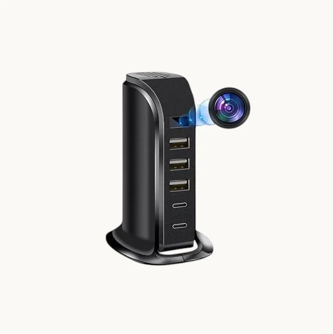
The single most important thing to understand before attempting a wake-up is this: do not use a fast charger, a PD charger, or a QC charger for this procedure.
When you connect a USB Power Delivery (PD) or Quick Charge (QC) charger to a device, the charger and device perform a rapid handshake negotiation to determine the optimal voltage and current. During this handshake — which takes place in the first 500 ms of connection — the charger may briefly output 9 V, 12 V, or up to 20 V before settling to a negotiated level.
For a device whose BMS is already in over-discharge lockout, this voltage spike can:
– Trigger the over-charge protection circuit, adding a secondary lockout layer
– Damage the protection MOSFET gate if the spike exceeds the IC’s absolute maximum rating
– In rare cases with very high-current chargers (65 W+ PD adapters), induce enough thermal stress on the charge controller IC to require factory repair
The correct charger is a standard USB-A charger rated at 5 V / 1 A with no negotiation protocols — the same charger included in every QZT retail box. Alternatively, a powered-on computer USB port is equally safe: USB 2.0 ports deliver 5 V at up to 500 mA, and USB 3.0 ports up to 900 mA, both with no voltage negotiation.
For voice recorders and pen cameras with USB-C ports, a USB-C cable connected to a 5 V / 1 A charger or PC USB-C port is safe. Do not use a USB-C PD charger.
Step 1 — Prepare the Correct Charger and Cable
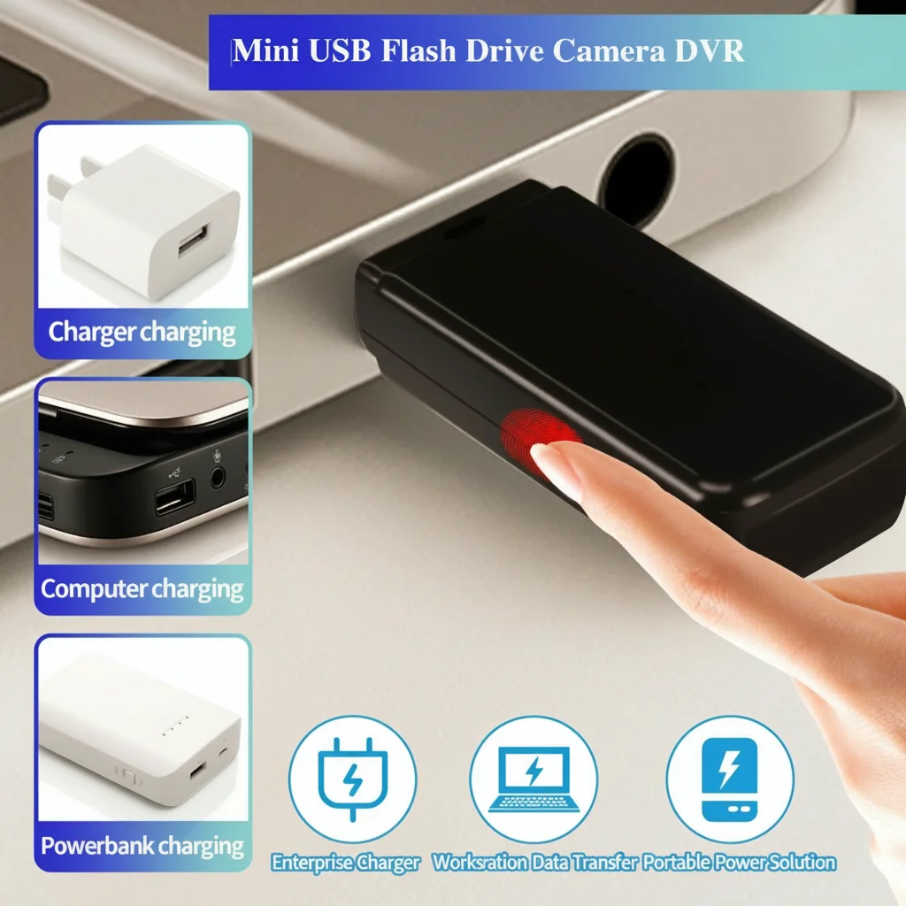
Before touching the device, confirm your power source:
Acceptable power sources (in order of preference):
1. The original OEM USB charger included in the device box (5 V / 1 A USB-A)
2. A computer’s rear USB-A port on the motherboard I/O panel
3. A standard USB-A wall adapter with no branding indicating PD or QC support
4. A powered USB 2.0 hub connected to a computer
Unacceptable power sources (never use):
– Any charger with “PD”, “Power Delivery”, “Quick Charge”, or “QC” on the label
– Laptop USB-C chargers rated above 20 W
– Any USB-A charger rated above 5 V / 2 A without verified no-negotiation design
– Power banks in “fast charge” or “PD out” mode
The OEM data cable matters. Use the cable that shipped with the device. Aftermarket “USB-C to USB-A” cables often swap the CC pin pull-down resistors, which can cause USB-C chargers to attempt PD negotiation even when connected to a USB-A port through an adapter. The OEM cable has the correct 56 kΩ pull-down on CC1 to signal a standard USB device.
Connect the charger to power first (plug it into the wall or turn on the PC), then connect the cable to the device. This order reduces the chance of a transient voltage spike reaching the BMS during cable insertion.
Step 2 — Trickle Charging: The 2-Hour Activation Wait
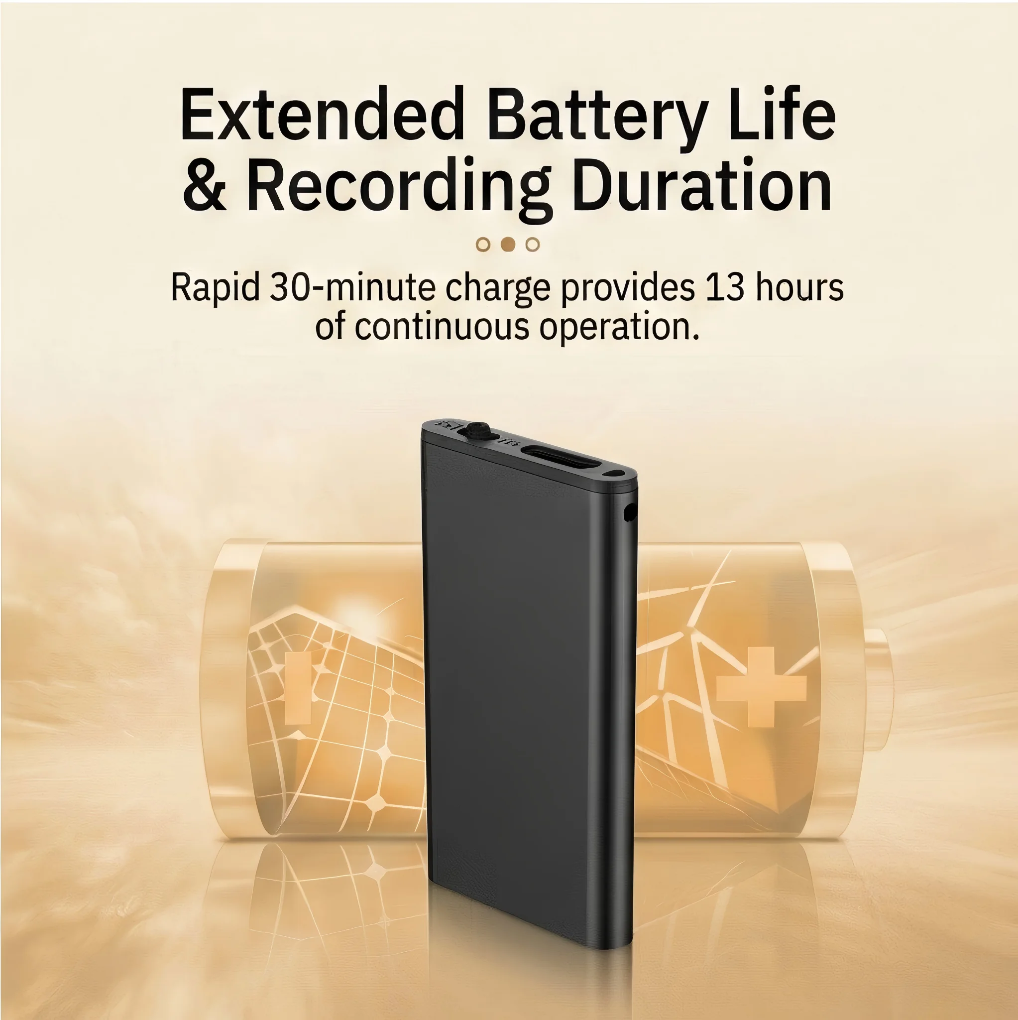
With the device connected to a safe 5 V / 1 A power source, you enter the trickle activation phase. This is the most counterintuitive step: the device will appear completely dead.
Do not panic if the LED does not light up. This is expected. In over-discharge lockout, the protection circuit has disconnected the LED as well as the main load — the BMS is consuming microamperes of current from the cell solely to monitor voltage. The trickle charge must first raise the cell voltage from its resting level (typically 2.8–3.1 V) up to the BMS reconnection threshold of 3.3–3.4 V before any circuit — including the LED — will receive power.
Minimum activation time: 2 hours of continuous connection to 5 V / 1 A. This is not a soft guideline. At 500 mA (PC USB 2.0 port), 2 hours delivers approximately 1 Wh of energy into a cell that may be sitting at 3.0 V at 30% SOC. This is sufficient to cross the reconnection threshold in most cases. For larger capacity cells (power bank cameras with 3,000–10,000 mAh cells), 3–4 hours may be necessary.
During the activation wait:
– Do not press any buttons on the device — pressing the power button on a locked-out BMS does nothing and may confuse the charge controller’s state machine
– Do not unplug and replug the cable repeatedly — each connection creates a tiny inrush transient; consistent 2-hour contact is better
– Do not check the LED every 5 minutes — leave the device completely undisturbed
– Place the device near the charger but not on a heat source; room temperature (20–25°C) is optimal
What happens at the 2-hour mark: The BMS monitors cell voltage through a comparator circuit. When the voltage rises above approximately 3.35 V — the recovery threshold — the protection MOSFET closes and reconnects the main load rail. At this moment, the device begins its boot sequence. The LED will typically flash red or cycle through a color sequence (red → blue, or slow blink → fast blink) to indicate the charge controller has recognized the cell and is actively charging.
If the LED does not appear after 3 hours on a 1 A charger, proceed to Step 3.
Step 3 — If the LED Still Does Not Light After 3 Hours
There are two possible reasons the device has not responded after a full 3-hour trickle charge:
Reason 1: The cell has degraded past the recovery voltage. Lithium cells stored at high temperature (>30°C) or at low charge for extended periods (>12 months) can undergo accelerated capacity fade. If the cell’s internal resistance has increased to the point where the voltage at 500 mA charge current never rises above the recovery threshold, the BMS never reconnects. The cell may still hold some capacity — but at a higher voltage than 3.2 V, in a chemical state the charger cannot address without exceeding safe charge rates.
Recovery attempt for degraded cells: Connect the device to a USB 5 V / 1 A power source and leave it for 12–24 hours continuously. Some cells in this borderline state require an extended low-rate charge to reach the recovery voltage. If after 24 hours there is still no LED response, the cell has failed and the device requires battery replacement under warranty.
Reason 2: The charge port or charge controller IC has failed. In rare cases, the device’s internal charge controller (typically a TP4056 or equivalent for single-cell LiPo applications) can fail open — delivering no charge current even though the USB voltage is present. The device then enters a permanent lockout because the BMS never sees voltage recovery.
How to distinguish: After 3 hours of trickle charge with no LED, feel the USB port area on the device body. If it is noticeably warm, current is flowing and the issue is chemical (proceed with 24-hour extended charge). If the area is room temperature, no current is flowing — the charge circuit has failed.
Charging circuit failure on QZT products is covered under warranty. Do not attempt to open the device to bypass the charge controller — the外壳 (enclosure) is sealed to maintain the covert appearance, and breaking the seal voids the warranty. Contact your distributor with the device serial number for a replacement unit.
Step 4 — Confirming Full Recovery and Completing the First Charge

Once the LED activates, allow the device to charge to full. The charging indicator for most QZT pen cameras and voice recorders follows this sequence:
Charging state:
– Solid red LED → battery below 80% state-of-charge, actively charging
– Solid blue LED → battery above 80%, fast charge phase
– LED off (while still connected to power) → battery above 95%, in charge-complete trickle mode
– LED blinking red → low battery (below 20%), charge to full before use
Full charge time from empty to complete: 2–3 hours for pen cameras and voice recorders (500–800 mAh cells). 6–8 hours for power bank cameras (3,000–10,000 mAh cells).
Before using the device for a recording session: After the LED confirms full charge, disconnect the charger, wait 5 minutes, then power on the device normally. This pause allows the charge controller to close cleanly and the cell voltage to settle. Attempting to record while the charge controller is still in termination mode can cause a brief voltage dip that interrupts the recording.
B2B Warehouse Maintenance Protocol: Preventing Protection Lockout at Scale
For distributors managing inventory of 10 or more covert recording units, the following maintenance schedule prevents over-discharge protection lockout across the entire stock — eliminating the cost and logistics burden of “dead on arrival” units returned by end customers.
Every 3 months (quarterly):
1. Identify all units in warehouse stock by scanning the product serial number range for your lot.
2. For each unit: connect to a 5 V / 1 A USB power source for 30–60 minutes. This is a maintenance charge, not a full cycle. The target is to restore the cell to approximately 50% state-of-charge.
3. Disconnect after the maintenance charge. Do not leave units on continuous charge in storage — a LiPo cell stored at 100% SOC ages 3× faster than one stored at 50% SOC at room temperature.
Why 50% is the optimal storage SOC. The Arrhenius equation governs lithium cell calendar aging: the rate of SEI layer growth on the anode (the primary aging mechanism) doubles for every 10°C increase in temperature and increases roughly 2× for every 10% increase in SOC above 50%. A cell stored at 50% SOC at 25°C will retain approximately 90% of its rated capacity after 12 months. A cell stored at 100% SOC at 25°C will retain approximately 75–80% after the same period.
Temperature matters equally. Maintain warehouse storage temperature between 15°C and 25°C. Cells stored at 35°C (common in non-climate-controlled storage facilities in summer) lose approximately 20% additional capacity per year compared to 25°C storage, regardless of SOC. Climate-controlled storage is a worthwhile investment for high-value covert recording inventory.
Recording a maintenance log. For each quarterly maintenance session, record the serial number, date, and charge duration in a spreadsheet. This log serves two purposes: it documents the maintenance schedule for warranty claims, and it provides early warning for units that consistently require longer maintenance charges — a potential indicator of elevated self-discharge rate that may require batch recall.
Często zadawane pytania
Q: My device shows a red blinking LED but will not power on. Is this the same lockout issue?
A: A blinking LED indicates the charge controller is active but the battery is critically low (below 15% SOC). Connect it to 5 V / 1 A immediately and wait 30–60 minutes for the cell to reach a safe operating voltage. A solid red LED after 15 minutes of charging confirms the battery has recovered enough to attempt a power-on.
Q: Can I use a power bank to charge a device in over-discharge lockout?
A: Yes — but only if the power bank does not have fast-charge output enabled. Some power banks default to 5 V / 1 A and are safe. However, many power banks (particularly those with USB-C PD or QC output) negotiate voltage before delivering current, which carries the same risk as using a fast charger. A simple test: if the power bank has a single USB-A port with no label, it is likely safe. If it has USB-C, multiple ports, or fast-charge branding, use a wall charger or PC USB port instead.
Q: How often should I charge a device that I use regularly?
A: For active-use devices, charge whenever the battery falls below 30% SOC (most QZT devices signal this with a slow blinking red LED). Avoid deep discharging below 10% regularly — while the BMS protects against over-discharge, repeated deep cycles accelerate capacity fade. The optimal charging habit is little and often: a 30-minute top-up every few days is gentler on the cell than a full 0→100% cycle.
P: Urządzenie uruchamia się po procedurze aktywacji, ale wyłącza się po tylko 10 minutach nagrywania. Czy bateria jest uszkodzona?
O: Bateria, która akceptuje ładowanie i uruchamia urządzenie, ale szybko się wyłącza, doświadcza utrata kapacytności z powodu głębokiego rozładowania. Komórka utraciła użyteczne amperogodziny, nie z powodu blokady ochronnej, ale z powodu degradacji chemicznej podczas okresu przechowywania przy niskim napięciu. W większości przypadków można to naprawić poprzez 3–5 pełnych cyklów ładowania, gdy jon litu ponownie rozpraszają się w elektrodach. Jeśli czas pracy nie poprawi się po 5 pełnych cyklach, oznacza to trwałą redukcję kapacytności komórki i bateria wymaga wymiany.
P: Otrzymaliśmy partię 50 jednostek i 8 z nich nie pokazuje reakcji LED po 3 godzinach ładowania na ładowarce 5 V / 1 A. Czy to wada partii?
O: Wskaźnik awaryjności sub-20% przy pierwszym ładowaniu podtrzymującym mieści się w normalnej statystycznej zmienności dla partii przechowywanej 4–6 miesięcy bez uprzednego ładowania konserwacyjnego. Spróbuj zastosować procedurę ładowania rozszerzonego do 24 godzin dla tych 8 jednostek. Jeśli 6 lub więcej odzyska funkcjonalność, partia jest w porządku — potrzebowały tylko dłuższej aktywacji. Jeśli odzyska się mniej niż 6, zanotuj numery seryjne i skontaktuj się z dystrybutorem QZT: powtarzające się awarie w tej samej partii mogą wskazywać na różnice w partii komponentów kontrolera ładowania, które są objęte umową gwarancyjną dystrybutora.
Wnioski
Ukryte urządzenie nagrywające, które nie uruchamia się po miesiącach przechowywania, niemal nigdy nie jest zepsute — jest chronione. Odcięcie przez układ zarządzania baterią (BMS) przy nadmiernym rozładowaniu jest celowym, korzystnym zabezpieczeniem, które chroni komórki litowe przed osiągnięciem poziomów napięcia związanych z metalicznym osadzaniem litu i termicznym rozbieganiem.
Procedura odzyskania jest prosta: podłącz do standardowej ładowarki 5 V / 1 A (nigdy PD lub QC), pozostaw urządzenie bez ingerencji minimum 2 godziny i czekaj na pojawienie się diody LED. Jeśli urządzenie nie reaguje po 3 godzinach, zwiększ czas do 24 godzin. Utrzymujący się brak reakcji po 24 godzinach wskazuje na awarię układu ładowania wymagającej serwisu gwarancyjnego.
Dla dystrybutorów B2B, ekonomicznym podejściem jest profilaktyka: ładowanie konserwacyjne przez 30–60 minut co kwartał do stanu SOC 50%, przechowywanie w temperaturze pokojowej oraz prowadzenie dziennika konserwacji według numerów seryjnych. Ta jedna praktyka eliminuje większość zwrotów z powodu nadmiernego rozładowania, redukuje koszty gwarancyjne i zapewnia, że każda jednostka otrzymana przez klienta jest gotowa do nagrywania w dniu dostawy.
Dla użytkowników jednostkowych wnioski są takie same jak dla zarządców magazynów: baterie litowe wymagają uwagi co kilka miesięcy, nie tylko przy pierwszym użyciu. Urządzenie przechowywane w szufladzie przez sześć miesięcy bez ładowania podtrzymującego wymagać będzie opisanej procedury aktywacji przez 2 godziny. Urządzenie poddawane ładowaniu konserwacyjnym przez 30 minut co trzy miesiące uruchomi się natychmiast zawsze.

 English
  Italiano
  Deutsch
  Français
  Español
  Polski