
Este es el paso más contradictorio: el dispositivo parecerá completamente muerto.
If your spy camera, voice recorder, or covert recording device has been sitting in a warehouse shelf for three months or longer, and it now refuses to power on, shows no LED indicator, and does not respond to any button press — the device is almost certainly not dead. It is in over-discharge protection lockout, a built-in safety mechanism that has shut down the battery to prevent permanent damage.
This guide explains why the lockout occurs, how the Battery Management System (BMS) enforces it at the hardware level, and exactly how to safely wake the device up using trickle charging. It also covers the maintenance protocol that warehouse distributors and B2B resellers should follow to prevent this issue across their inventory.
Why Your Battery Enters Protection Lockout: The BMS Mechanism
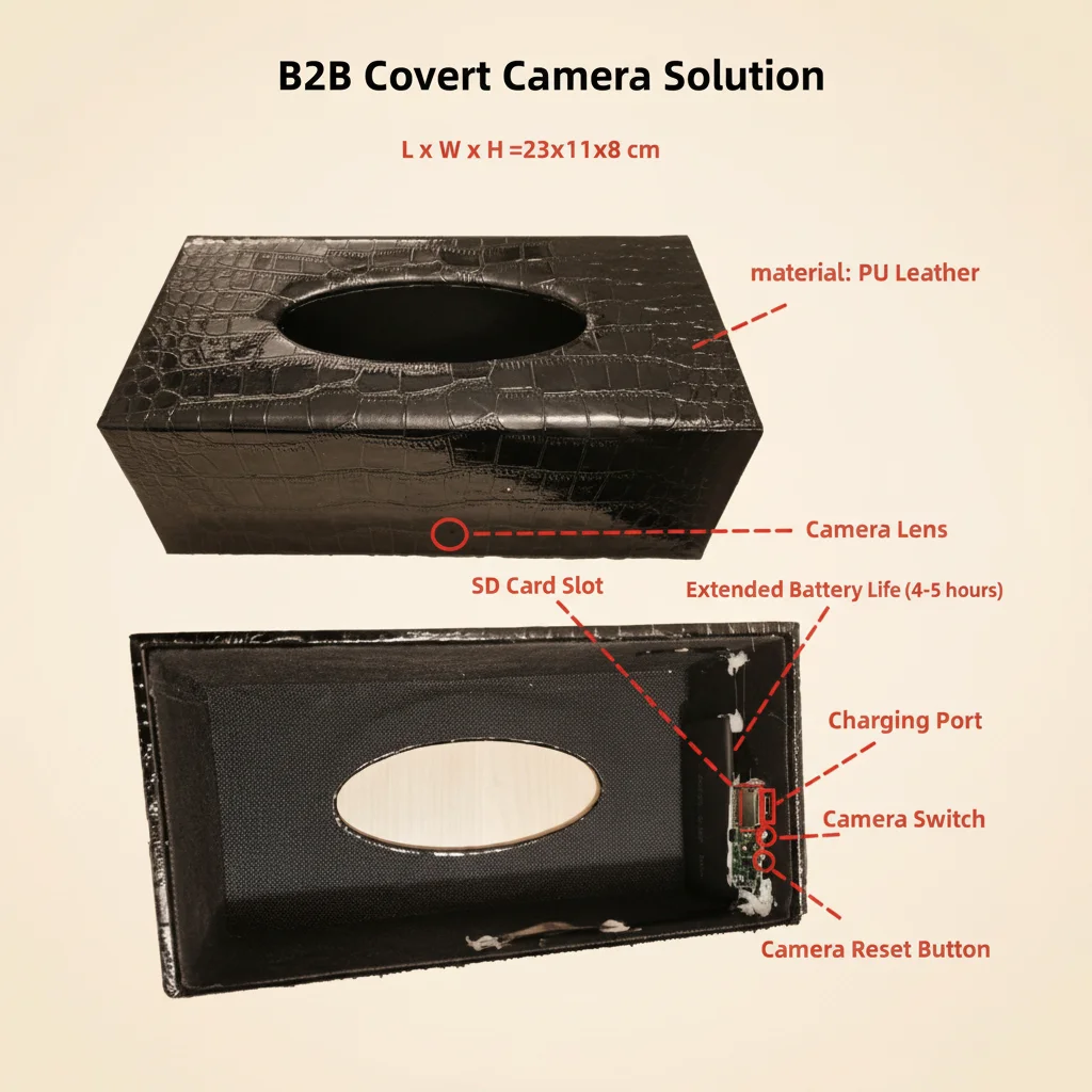
Todas las celdas de polímero de litio (LiPo) y de iones de litio (Li-ion) utilizadas en dispositivos de grabación encubiertos QZT incorporan un Sistema de Gestión de Baterías a nivel de hardware — un CI de protección dedicado integrado en la placa de alimentación del dispositivo. Esto no es firmware ni software: es un circuito físico que responde a umbrales de voltaje más rápido de lo que cualquier sistema operativo puede intervenir.
The BMS enforces three hard cutoffs to prevent hazardous conditions:
Over-discharge cutoff (the lockout you are experiencing). When the cell voltage falls below 3.2 V during a storage period, the protection MOSFET disconnects the negative terminal from the rest of the circuit. The device cannot draw any current — even in standby. This cutoff activates at approximately 70% state-of-charge for a typical 3.7 V LiPo cell, which means a device left at 50% charge and stored for 4–6 months without a maintenance top-up cycle will reliably trigger this protection.
Over-charge cutoff. If a cell reaches 4.25 V during charging, the BMS cuts the charge path to prevent thermal runaway. QZT devices incorporate this protection so that using any compliant 5 V USB power source is safe, even if the charger behaves unexpectedly.
Short-circuit and over-current cutoff. Any current draw exceeding approximately 3 A for more than 10 ms triggers an immediate disconnection. High-power fast chargers (PD, QC) can produce inrush current spikes during initial connection negotiation that exceed this threshold, causing the BMS to enter a secondary lockout on top of the existing over-discharge lockout — making the device significantly harder to recover.
El bloqueo por sobredescarga es la causa más común de informes de “muerto al llegar” de distribuidores que almacenan inventario sin gestión activa de energía. No es un defecto; es el BMS haciendo exactamente lo para lo que fue diseñado.
Why Fast Chargers Will Make This Worse
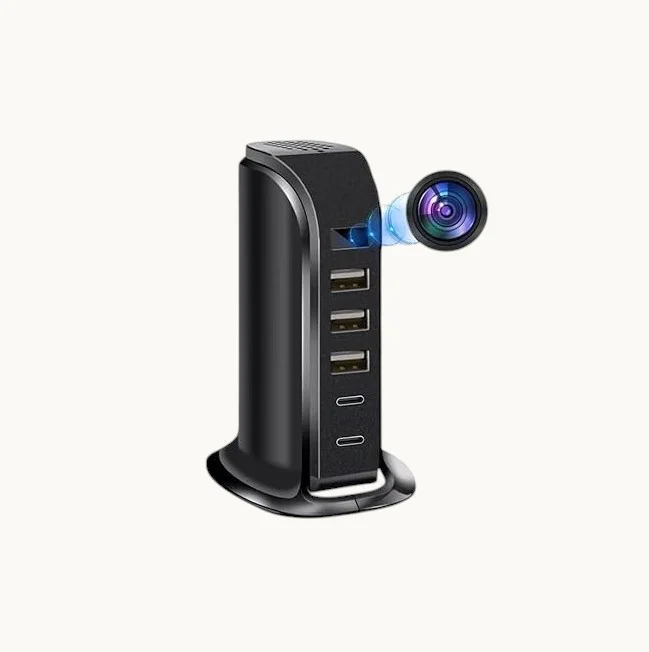
The single most important thing to understand before attempting a wake-up is this: do not use a fast charger, a PD charger, or a QC charger for this procedure.
When you connect a USB Power Delivery (PD) or Quick Charge (QC) charger to a device, the charger and device perform a rapid handshake negotiation to determine the optimal voltage and current. During this handshake — which takes place in the first 500 ms of connection — the charger may briefly output 9 V, 12 V, or up to 20 V before settling to a negotiated level.
For a device whose BMS is already in over-discharge lockout, this voltage spike can:
– Activar el circuito de protección contra sobrecarga, añadiendo una capa secundaria de bloqueo
– Dañar la puerta del MOSFET de protección si el pico supera la clasificación máxima absoluta del CI
– En casos raros con cargadores de corriente muy alta (adaptadores PD de 65 W+), inducen suficiente estrés térmico en el IC del controlador de carga para requerir reparación de fábrica
The correct charger is a standard USB-A charger rated at 5 V / 1 A with no negotiation protocols — the same charger included in every QZT retail box. Alternatively, a powered-on computer USB port is equally safe: USB 2.0 ports deliver 5 V at up to 500 mA, and USB 3.0 ports up to 900 mA, both with no voltage negotiation.
For voice recorders and pen cameras with USB-C ports, a USB-C cable connected to a 5 V / 1 A charger or PC USB-C port is safe. Do not use a USB-C PD charger.
Step 1 — Prepare the Correct Charger and Cable
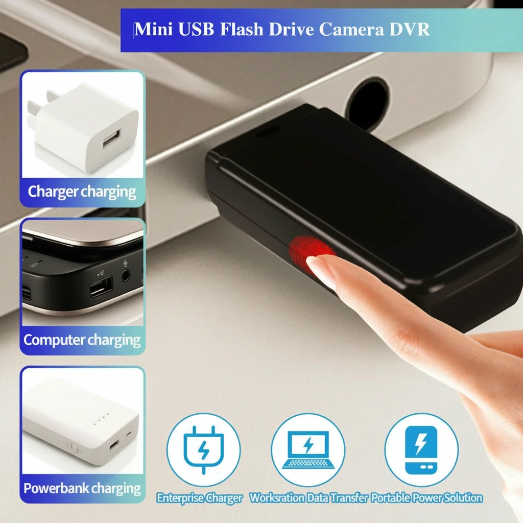
Before touching the device, confirm your power source:
Acceptable power sources (in order of preference):
1. The original OEM USB charger included in the device box (5 V / 1 A USB-A)
2. Un puerto USB-A trasero de la placa base en el panel E/S de un ordenador
3. A standard USB-A wall adapter with no branding indicating PD or QC support
4. A powered USB 2.0 hub connected to a computer
Unacceptable power sources (never use):
– Cualquier cargador con “PD”, “Power Delivery”, “Quick Charge” o “QC” en la etiqueta
– Cargadores USB-C para portátiles clasificados por encima de 20 W
– Cualquier cargador USB-A clasificado por encima de 5 V / 2 A sin diseño verificado sin negociación
– Baterías externas en modo “carga rápida” o “salida PD”
The OEM data cable matters. Utilice el cable que venía con el dispositivo. Los cables de reemplazo “USB-C a USB-A” a menudo intercambian las resistencias de pull-down del pin CC, lo que puede hacer que los cargadores USB-C intenten negociar PD incluso cuando están conectados a un puerto USB-A a través de un adaptador. El cable OEM tiene la resistencia de pull-down correcta de 56 kΩ en CC1 para indicar un dispositivo USB estándar.
Connect the charger to power first (plug it into the wall or turn on the PC), then connect the cable to the device. This order reduces the chance of a transient voltage spike reaching the BMS during cable insertion.
Step 2 — Trickle Charging: The 2-Hour Activation Wait
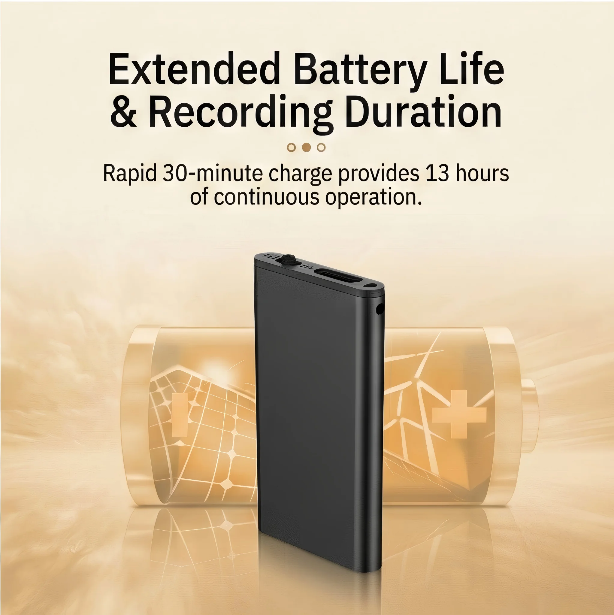
With the device connected to a safe 5 V / 1 A power source, you enter the trickle activation phase. This is the most counterintuitive step: the device will appear completely dead.
A: Sí — pero solo si el banco de energía no tiene la salida de carga rápida activada. Algunos bancos de energía tienen por defecto 5 V / 1 A y son seguros. Sin embargo, muchos bancos de energía (particularmente aquellos con salida USB-C PD o QC) negociarán la voltaje antes de entregar corriente, lo cual lleva el mismo riesgo que usar un cargador rápido. Una prueba simple: si el banco de energía tiene un solo puerto USB-A sin etiqueta, probablemente es seguro. Si tiene USB-C, múltiples puertos, o marca de carga rápida, usa un cargador de pared o un puerto USB de PC en lugar. This is expected. In over-discharge lockout, the protection circuit has disconnected the LED as well as the main load — the BMS is consuming microamperes of current from the cell solely to monitor voltage. The trickle charge must first raise the cell voltage from its resting level (typically 2.8–3.1 V) up to the BMS reconnection threshold of 3.3–3.4 V before any circuit — including the LED — will receive power.
Minimum activation time: 2 hours of continuous connection to 5 V / 1 A. This is not a soft guideline. At 500 mA (PC USB 2.0 port), 2 hours delivers approximately 1 Wh of energy into a cell that may be sitting at 3.0 V at 30% SOC. This is sufficient to cross the reconnection threshold in most cases. For larger capacity cells (power bank cameras with 3,000–10,000 mAh cells), 3–4 hours may be necessary.
During the activation wait:
– No presionar ningún botón del dispositivo — presionar el botón de encendido en un BMS bloqueado no hace nada y puede confundir la máquina de estados del controlador de carga
– No desenchufar y volver a enchufar el cable repetidamente — cada conexión crea una pequeña sobretensión transitoria de entrada; un contacto constante de 2 horas es mejor
– No verificar el LED cada 5 minutos — dejar el dispositivo completamente sin perturbar
– Colocar el dispositivo cerca del cargador pero no sobre una fuente de calor; temperatura ambiente (20–25°C) es óptima
What happens at the 2-hour mark: The BMS monitors cell voltage through a comparator circuit. When the voltage rises above approximately 3.35 V — the recovery threshold — the protection MOSFET closes and reconnects the main load rail. At this moment, the device begins its boot sequence. The LED will typically flash red or cycle through a color sequence (red → blue, or slow blink → fast blink) to indicate the charge controller has recognized the cell and is actively charging.
If the LED does not appear after 3 hours on a 1 A charger, proceed to Step 3.
Step 3 — If the LED Still Does Not Light After 3 Hours
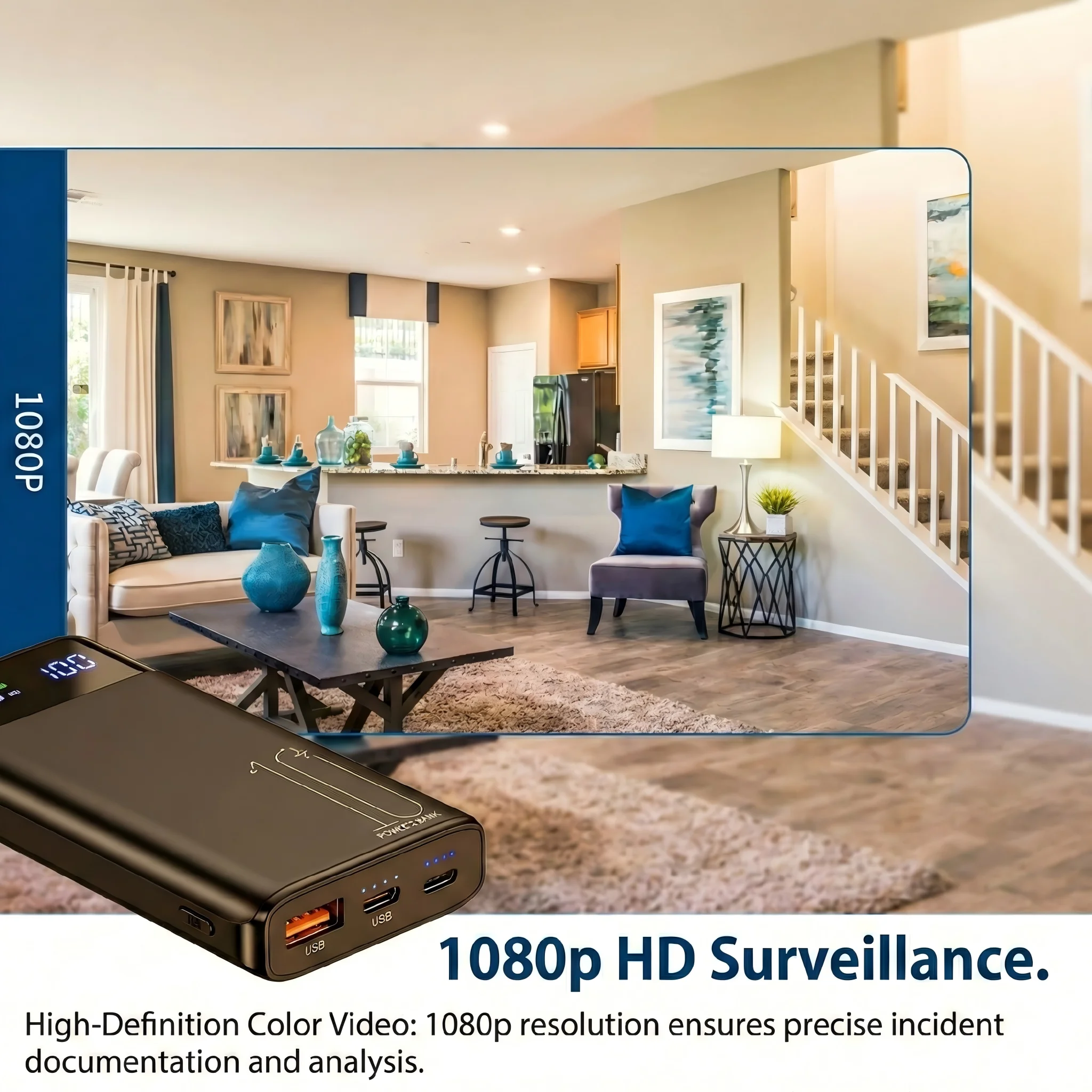
There are two possible reasons the device has not responded after a full 3-hour trickle charge:
Reason 1: The cell has degraded past the recovery voltage. Las celdas de litio almacenadas a alta temperatura (>30°C) o con carga baja durante períodos prolongados (>12 meses) pueden sufrir una pérdida acelerada de capacidad. Si la resistencia interna de la celda ha aumentado hasta el punto en que el voltaje con una corriente de carga de 500 mA nunca supera el umbral de recuperación, el BMS nunca se reconecta. La celda aún puede retener cierta capacidad — pero a un voltaje superior a 3.2 V, en un estado químico que el cargador no puede abordar sin exceder las tasas de carga seguras.
Recovery attempt for degraded cells: Connect the device to a USB 5 V / 1 A power source and leave it for 12–24 hours continuously. Some cells in this borderline state require an extended low-rate charge to reach the recovery voltage. If after 24 hours there is still no LED response, the cell has failed and the device requires battery replacement under warranty.
Reason 2: The charge port or charge controller IC has failed. En casos raros, el controlador de carga interno del dispositivo (normalmente un TP4056 o equivalente para aplicaciones de LiPo de una sola celda) puede fallar en abierto — no suministrando corriente de carga aunque esté presente el voltaje USB. El dispositivo entra entonces en un bloqueo permanente porque el BMS nunca ve recuperación de voltaje.
How to distinguish: After 3 hours of trickle charge with no LED, feel the USB port area on the device body. If it is noticeably warm, current is flowing and the issue is chemical (proceed with 24-hour extended charge). If the area is room temperature, no current is flowing — the charge circuit has failed.
Charging circuit failure on QZT products is covered under warranty. Do not attempt to open the device to bypass the charge controller — the外壳 (enclosure) is sealed to maintain the covert appearance, and breaking the seal voids the warranty. Contact your distributor with the device serial number for a replacement unit.
Step 4 — Confirming Full Recovery and Completing the First Charge

Once the LED activates, allow the device to charge to full. The charging indicator for most QZT pen cameras and voice recorders follows this sequence:
Charging state:
– LED rojo fijo → batería por debajo del estado de carga 80%, cargando activamente
– LED azul fijo → batería por encima de 80%, fase de carga rápida
– LED apagado (mientras sigue conectado a la alimentación) → batería por encima de 95%, en modo de carga completa por goteo
– LED parpadeando en rojo → batería baja (por debajo de 20%), cargar completamente antes de usar
Full charge time from empty to complete: 2–3 hours for pen cameras and voice recorders (500–800 mAh cells). 6–8 hours for power bank cameras (3,000–10,000 mAh cells).
Before using the device for a recording session: After the LED confirms full charge, disconnect the charger, wait 5 minutes, then power on the device normally. This pause allows the charge controller to close cleanly and the cell voltage to settle. Attempting to record while the charge controller is still in termination mode can cause a brief voltage dip that interrupts the recording.
B2B Warehouse Maintenance Protocol: Preventing Protection Lockout at Scale
Para distribuidores que gestionan inventarios de 10 o más unidades de grabación encubiertas, el siguiente programa de mantenimiento evita el bloqueo por sobredescarga en todo el stock — eliminando el costo y la carga logística de unidades “muertas al llegar” devueltas por los clientes finales.
Every 3 months (quarterly):
1. Identify all units in warehouse stock by scanning the product serial number range for your lot.
2. For each unit: connect to a 5 V / 1 A USB power source for 30–60 minutes. This is a maintenance charge, not a full cycle. The target is to restore the cell to approximately 50% state-of-charge.
3. Disconnect after the maintenance charge. Do not leave units on continuous charge in storage — a LiPo cell stored at 100% SOC ages 3× faster than one stored at 50% SOC at room temperature.
Why 50% is the optimal storage SOC. The Arrhenius equation governs lithium cell calendar aging: the rate of SEI layer growth on the anode (the primary aging mechanism) doubles for every 10°C increase in temperature and increases roughly 2× for every 10% increase in SOC above 50%. A cell stored at 50% SOC at 25°C will retain approximately 90% of its rated capacity after 12 months. A cell stored at 100% SOC at 25°C will retain approximately 75–80% after the same period.
Temperature matters equally. Maintain warehouse storage temperature between 15°C and 25°C. Cells stored at 35°C (common in non-climate-controlled storage facilities in summer) lose approximately 20% additional capacity per year compared to 25°C storage, regardless of SOC. Climate-controlled storage is a worthwhile investment for high-value covert recording inventory.
Recording a maintenance log. For each quarterly maintenance session, record the serial number, date, and charge duration in a spreadsheet. This log serves two purposes: it documents the maintenance schedule for warranty claims, and it provides early warning for units that consistently require longer maintenance charges — a potential indicator of elevated self-discharge rate that may require batch recall.
Preguntas frecuentes
Q: My device shows a red blinking LED but will not power on. Is this the same lockout issue?
A: A blinking LED indicates the charge controller is active but the battery is critically low (below 15% SOC). Connect it to 5 V / 1 A immediately and wait 30–60 minutes for the cell to reach a safe operating voltage. A solid red LED after 15 minutes of charging confirms the battery has recovered enough to attempt a power-on.
Q: Can I use a power bank to charge a device in over-discharge lockout?
A: Yes — but only if the power bank does not have fast-charge output enabled. Some power banks default to 5 V / 1 A and are safe. However, many power banks (particularly those with USB-C PD or QC output) negotiate voltage before delivering current, which carries the same risk as using a fast charger. A simple test: if the power bank has a single USB-A port with no label, it is likely safe. If it has USB-C, multiple ports, or fast-charge branding, use a wall charger or PC USB port instead.
Cómo activar una batería de cámara espía almacenada durante mucho tiempo
A: For active-use devices, charge whenever the battery falls below 30% SOC (most QZT devices signal this with a slow blinking red LED). Avoid deep discharging below 10% regularly — while the BMS protects against over-discharge, repeated deep cycles accelerate capacity fade. The optimal charging habit is little and often: a 30-minute top-up every few days is gentler on the cell than a full 0→100% cycle.
Q: The device powers on after the wake-up procedure but shuts down after only 10 minutes of recording. Is the battery damaged?
A: A battery that accepts a charge and boots the device but dies quickly is experiencing capacity loss from deep discharge. The cell has lost usable ampere-hours, not from a protection lockout but from the chemistry degrading during the low-voltage storage period. This is recoverable over 3–5 full charge cycles in most cases, as the lithium ions redistribute within the electrodes. If the runtime does not improve after 5 full cycles, the cell capacity has permanently reduced and the battery requires replacement.
Q: We received a batch of 50 units and 8 of them show no LED response after 3 hours on a 5 V / 1 A charger. Is this a batch defect?
A: A sub-20% failure rate at first trickle activation is within normal statistical variation for a batch stored 4–6 months without prior maintenance charge. Try the 24-hour extended charge procedure for these 8 units. If 6 or more of them recover, the batch is fine — they just needed longer activation. If fewer than 6 recover, document the serial numbers and contact your QZT distributor: consistent failures in the same batch may indicate a charge controller component lot variance, which is covered under the distributor warranty agreement.
Conclusión
Un dispositivo de grabación encubierto que no se enciende después de meses en almacenamiento casi nunca está roto — está protegido. El corte por sobredescarga del Sistema de Gestión de Baterías es una característica de seguridad deliberada y beneficiosa que evita que las celdas de litio alcancen los niveles de voltaje asociados con la formación de litio metálico y la fuga térmica.
The recovery procedure is straightforward: connect to a standard 5 V / 1 A charger (never PD or QC), leave the device undisturbed for 2 hours minimum, and wait for the LED to appear. If the device does not respond after 3 hours, extend to 24 hours. Persistent non-response after 24 hours indicates a charge circuit failure that requires warranty service.
For B2B distributors, the economically rational approach is prevention: quarterly 30–60 minute maintenance charges to 50% SOC, storage at room temperature, and a maintenance log by serial number. This single practice eliminates the majority of over-discharge returns, reduces warranty costs, and ensures that every unit your customer receives is ready to record on the day it arrives.
For single-unit users, the takeaway is the same as for inventory managers: lithium batteries need attention every few months, not just at first use. A device put into a drawer for six months without a top-up charge will require the 2-hour wake-up procedure described above. A device given a 30-minute maintenance charge every three months will power on immediately every time.

 English
  Italiano
  Deutsch
  Français
  Español
  Polski