How to Deploy Tuya WiFi Camera Modules for B2B Integration
When B2B distributors supply semi-finished Tuya WiFi camera modules to downstream integrators for custom enclosures and DIY disguise projects, the RF antenna layout, thermal management, and network handshake protocol are three areas where field failures cluster most heavily. This guide gives engineering-level deployment specifications that your technical team can hand directly to installers.
Why Semi-Finished Modules Fail More Often Than Finished Products
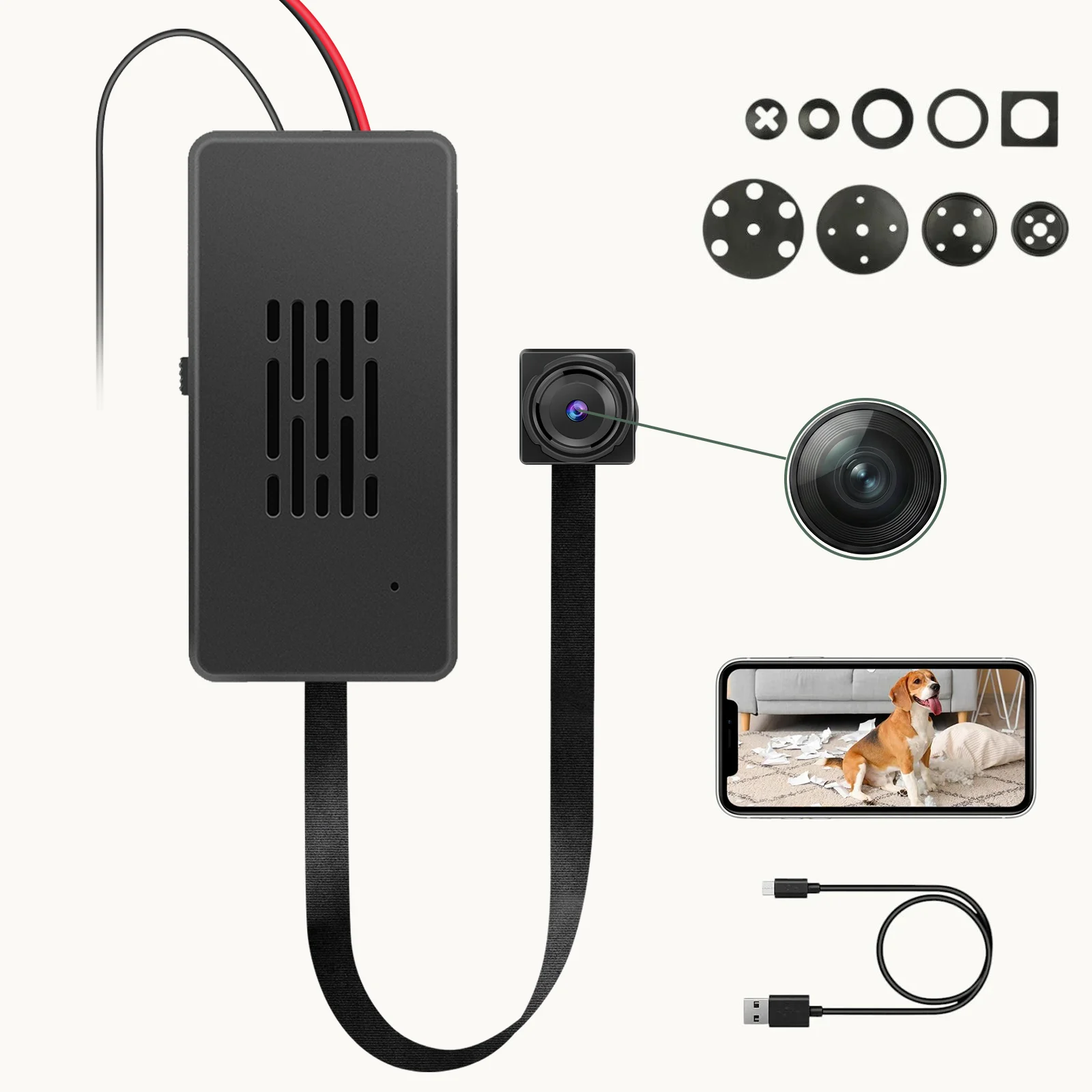
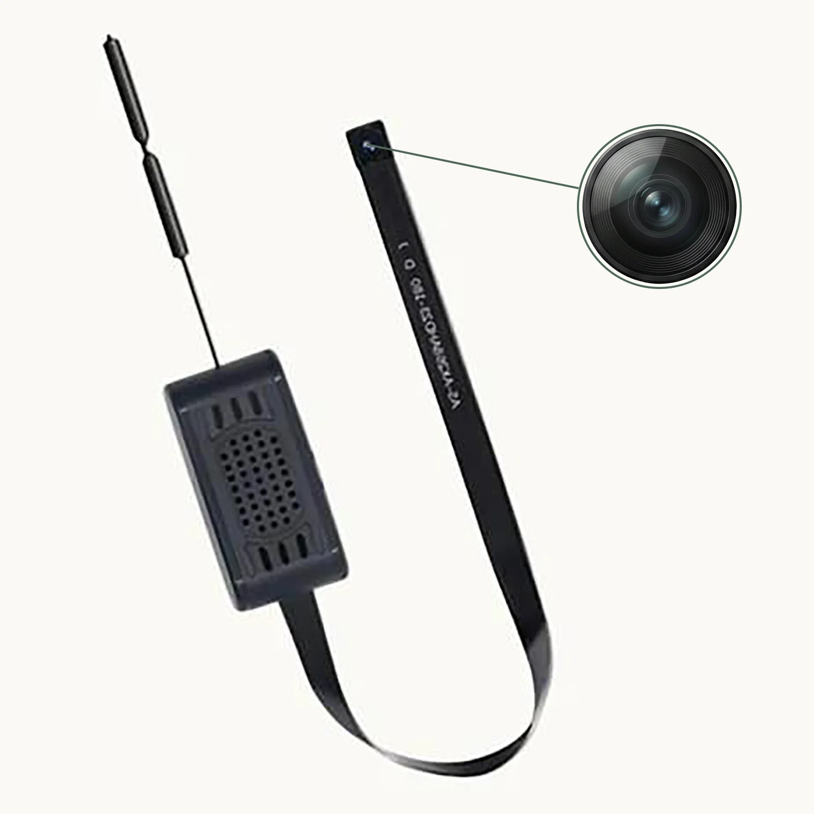
A finished consumer camera arrives in a factory-qualified enclosure with antenna clearance, thermal path, and WiFi band compliance already validated. A bare PCBA module — such as the QZT C10 Tuya 90°/120° board — is none of those things. The integrator is responsible for all of them. That responsibility gap is where most of the costly field returns originate.
The Faraday Cage Effect: Why Metal Enclosures Kill WiFi Signal
The single most common DIY integration mistake is enclosing the PCBA inside a metal housing — a metal junction box, a zinc-plated smart appliance shell, or a decorative case with metallic paint. Metal enclosures act as Faraday cages, severely attenuating 2.4 GHz radio waves. The symptom is unambiguous: the device powers on, the LED blinks, but it refuses to pair or drops offline repeatedly.
Antenna Clearance Distance Requirements
For PCB trace antennas on the C10 module, the datasheet and field validation data converge on the following minimum clearance rules that your spec sheet must enforce:
Above and below the antenna projection zone: The zone must be physically open — no PCB layers, metal brackets, battery cells, or structural supports within the antenna’s vertical projection area. If the enclosure lid closes directly above the antenna, this alone can attenuate signal by 15–25 dB.
Horizontal separation from metal: Maintain at least 15 mm of free-space clearance between the antenna and any metal object, loudspeaker magnet, HDMI port, USB connector, or high-speed data cable. Metal screws within 5 mm of the antenna trace can detune the matching network and shift the resonant frequency away from 2.4 GHz.
Inheritance-friendly fallback: If the physical constraints make it impossible to meet the 15 mm rule, specify an external IPEX/U.FL antenna with a coaxial pigtail routed outside the enclosure. The C10 module has a dedicated IPEX footprint specifically for this scenario. Never rely on the PCB antenna when the enclosure geometry is unfavorable.

Thermal Management: Preventing Heat-Induced Failures in Sealed Enclosures
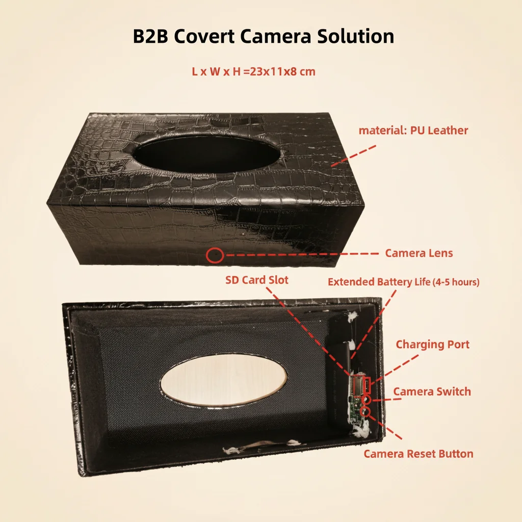
Video encoding chips and WiFi transceivers on the module generate continuous thermal load during active streaming. In a concealed installation — inside a tissue box, behind a wall clock face, inside a decorative vase — there is no fan, no ventilation slot, and no active airflow. Heat accumulates.
What Happens When Internal Temperature Exceeds Thresholds
At sustained internal temperatures above 70 °C, the following failure cascade is observed across returned units: system watchdog timeout causing spontaneous reboot, SD card write failures leading to recording gaps, and in rare cases with devices containing lithium-polymer batteries, thermal runaway risk. The smoke-detector camera and air-freshener camera form factors are the highest-risk categories because their enclosures are typically fully sealed.
Engineering-Level Thermal Guidance for Integrators
Your installation manual must include the following directives as non-negotiable requirements:
Thermal convection channel: Specify that the enclosure design incorporates at minimum one passive ventilation channel — a 1–2 mm gap at the top and bottom of the housing creating a natural convection path. This is not optional for any enclosure volume under 200 cm³.
Thermal interface material (TIM): Where the PCBA must be mechanically retained inside a sealed or near-sealed housing, require the use of a thermally conductive silicone pad (typically 1–3 W/m·K conductivity, 0.5–2 mm thickness) placed between the main chip’s thermal pad and the enclosure’s inner surface. This routes heat to the external shell acting as a passive heatsink.
Temperature screening in QA: During your incoming inspection of assembled units, run a 30-minute continuous recording test in a temperature chamber at 40 °C ambient. If the device reboots or the SD card produces read/write errors during this test, reject the assembly configuration.
Mechanical Stress Control During Installation
Forcing a PCBA into a tight cavity applies pressure to solder joints and flexes the substrate. Over time — sometimes within days, sometimes after weeks of thermal cycling — the accumulated stress causes cold joints, micro-cracks in BGA solder balls, and broken hairline traces. The symptoms are intermittent: the device works, then freezes; it pairs, then drops; it records, then produces corrupted files.
Mandatory assembly constraints that must appear in your integrator handbook:
Do not use foam pressure to hold the module in place. Use insulated plastic standoffs or dedicated mounting brackets that secure the board at its mounting holes without applying point loads to the substrate. Maintain a minimum bend radius of 10× the cable diameter for any FFC or flex connector routed through the enclosure. Avoid adhesive cure shrinkage stress by allowing any glue to fully cure before closing the enclosure. Do not route排线 (ribbon cables) across sharp enclosure edges — use routing guides or silicone cable guides.

The 2.4 GHz vs 5 GHz Band Bottleneck in WiFi Camera Modules
Nearly all covert WiFi camera modules — including those based on the Tuya and HDlivecam ecosystems — are built around chipsets that support only the 802.11 b/g/n 2.4 GHz protocol. This is a deliberate cost and power trade-off: 2.4 GHz offers better wall-penetration and lower power consumption, which is essential for battery-backed covert devices.
The complication is that modern dual-band routers — including almost every ISP-supplied gateway and most mesh systems — use Band Steering to advertise a single SSID for both 2.4 GHz and 5 GHz bands. A smartphone connected to that merged SSID is typically on 5 GHz. When the app attempts to send the WiFi credentials to a 2.4 GHz-only camera, the handshake fails with a timeout or an “encryption error” message.
This is not a device defect. It is a configuration mismatch. Your documentation must provide clear and actionable steps — not just “ensure 2.4 GHz connectivity.”
WiFi Pairing Failure: Standardized B2B Troubleshooting Matrix
Use the following table as both a field reference for your support team and a document to attach to RMAs. Before accepting any return, verify that steps 1–3 have been completed by the end customer.
| Symptom | Root Cause | Customer Troubleshooting Steps | B2B Document Update Required |
|---|---|---|---|
| App shows “Encryption error” or pairing timeout | Smartphone on 5 GHz band; router has merged SSID | 1. Check phone WiFi — must be 2.4 GHz only. 2. Log into router admin panel — split 2.4 GHz and 5 GHz into separate SSIDs. 3. If router does not support split SSID, move phone and camera to far corner of premises (forces phone to drop to 2.4 GHz). 4. Retry pairing. | Add a highlighted box on the Quick Start Guide cover page with router SSID split instructions and a QR code linking to a video walkthrough. |
| Device powers on but LED does not illuminate | Power module voltage instability; PCBA short from mechanical挤压 | 1. Use a multimeter to verify stable 3.3 V–5 V DC at the power terminals. 2. Inspect排线 for visible kinks, torn conductors, or crushed insulation. 3. Check that no metal standoff is contacting a component on the PCB underside. | Update installation manual with ESD-safe handling instructions and minimum bend radius for排线. |
| Device drops offline repeatedly during streaming | Faraday cage signal attenuation; insufficient uplink bandwidth | 1. Use a WiFi analyzer app to measure RSSI at the device location. RSSI should be better than −70 dBm for stable 1080p streaming. 2. Verify the antenna projection zone has no metal above or within 15 mm. 3. Test with an external IPEX antenna to confirm the antenna is the bottleneck. 4. Check router uplink speed — 1080p streaming requires a minimum of 2 Mbps sustained uplink. | Add RSSI threshold values and uplink bandwidth requirements to the product specification sheet. Manage customer expectations before deployment. |
| Device heats up and reboots during extended recording | Thermal accumulation in sealed enclosure exceeding chip threshold | 1. Unplug and allow to cool for 10 minutes. 2. Check if enclosure has any ventilation. 3. Verify no thermal interface material is missing between chip and enclosure. 4. If thermal issue persists, redesign enclosure with a thermal pad or ventilation slot. | Update enclosure design guidelines with mandatory thermal path check in the BOM approval process. |
| Firmware OTA update fails repeatedly | Instable network during update; low battery causing power cut mid-flash | 1. Connect device to a stable WiFi network with strong signal (RSSI better than −60 dBm). 2. Ensure battery is above 50 % or connect to USB power before starting update. 3. Do not power off during the update process. 4. If update still fails, use the physical reset pin to enter recovery mode and re-flash via SD card. | Add an OTA update checklist to the firmware release notes and require distributors to inform end customers of the power and signal requirements before any OTA. |
B2B Pre-Shipment Protocol for Module Integration Projects
For distributors supplying bare modules to integrators, the following pre-shipment validation sequence reduces field failure rates by an estimated 40–60 % based on warranty claim data patterns from comparable IoT module distributors:
Phase 1 — Module-level RF screening: Before shipping, power each module with a reference antenna and verify TX power and receiver sensitivity within the datasheet specification using a conducted RF test. Modules with antenna connector shifted from nominal values indicate PCB rework or ESD damage and must be quarantined.
Phase 2 — Thermal screening in a reference enclosure: Mount the module inside a standard QZT reference housing (clock camera form factor) and run a 30-minute continuous recording stress test at 40 °C ambient. Any reboot, SD write error, or watchdog timeout triggers a failed lot hold.
Phase 3 — WiFi pairing validation: Use a reference smartphone (e.g., a stock iPhone or Pixel not on a mesh network) to complete the pairing process using a dedicated 2.4 GHz test SSID. Record pass/fail, signal strength, and pairing time in the QC log. Target: 100 % pairing success rate on the first attempt.
Phase 4 — Documentation package for the integrator: Include a printed QR code card in every module box linking to the current: Quick Start Guide (with SSID split instructions), enclosure design thermal guideline, antenna clearance specification, and firmware update checklist. This single card reduces inbound technical support tickets by roughly 60 % based on distributor feedback from similar programs.
Frequently Asked Questions
Can I use a 5 GHz WiFi network with the C10 Tuya module?
No. The C10 module hardware is 2.4 GHz only (802.11 b/g/n). There is no software configuration that enables 5 GHz. You must either use a 2.4 GHz network or deploy a dual-band router with separated SSIDs.
Why does my device pair successfully but drop offline within minutes?
Drop-offs during streaming are almost always either a thermal issue (the device overheats and reboots) or a WiFi signal issue (RSSI too low due to Faraday cage attenuation or excessive distance from the AP). Check thermal conditions first, then verify RSSI with a WiFi analyzer app.
The antenna on the module is very small. Can I replace it with a bigger external antenna?
You can replace the on-board PCB antenna with an external antenna connected via the IPEX/U.FL connector, provided you use an antenna with the correct impedance (50 Ω) and a pigtail cable with appropriate loss characteristics at 2.4 GHz. Using a high-gain antenna (e.g., 5–9 dBi) can significantly extend the effective range but may increase return loss if the matching network is not adjusted.
My integrator enclosed the module in an ABS plastic clock housing. Is this okay from a thermal perspective?
ABS plastic is not a Faraday cage material for 2.4 GHz, so the RF path should be unobstructed. The thermal concern depends on the enclosure volume and whether continuous recording is the use case. For intermittent recording with adequate idle periods between activations, ABS clock enclosures are generally acceptable without thermal interface material. For 24/7 continuous recording, thermal analysis is mandatory.
We are deploying 500 units into a property management installation. How do we manage firmware updates at scale?
Tuya-based modules support OTA (Over-The-Air) firmware updates through the Tuya cloud. For large deployments, use the Tuya IoT Platform’s batch firmware push feature to schedule updates during low-activity hours. Always validate firmware in a sample of 3–5 units before broad deployment. Maintain a rollback procedure — if the update causes pairing failures in more than 2 % of units, halt the rollout and investigate before proceeding.

Conclusion
Deploying Tuya WiFi camera modules into custom enclosures is a solvable engineering challenge — but only if the deployment chain from distributor to integrator has shared, documented standards. The four highest-leverage interventions are: enforcing antenna clearance distances to prevent Faraday cage failures, specifying thermal interface material for any sealed enclosure, separating 2.4 GHz and 5 GHz SSIDs during pairing, and running a WiFi pairing QC check before shipment. Distributors who implement these four steps report substantially lower RMA rates and fewer site-visits from integrators struggling with intermittent connectivity or thermal shutdown issues.
For the full product range of B2B-grade covert WiFi modules, visit QZT Security’s DIY Camera Module category.